
Vincent
Technical Sections: -Serial
Numbers/Production- Photo Gallery of
Models - Brakes
- Engine
Overhaul - Vincent
Engines - Wheels/Fenders
- Instruments -
Transmission -
Clutch - Magneto - Tank/Seat - Suspension
- Tools - Norvin -
Electrics-
Carburetors - Misc - Links -Vincent
Parts/Services Suppliers - Polishing/Cleaning
- Shipping Vincents-Electric
Starter - Paint/Transfers
Vincent
Motorcycle Electrics:
Alton generator testing - Feb 2015 from K17 So cal - S. O. SEZ by Dave
Marshall - I
looked into my charging problem on my Comet this month. I
contacted the maker, Alton, and they gave
me the following instructions on checking the Alton for output:
Do
not forget to check for ground/earthing issues.
Then please do the following basic controls using a multimeter (if
not
already done):
Two
static tests (engine off):
[1-1] Test for continuity
between the 2 wires from the AC generator.
There should be CONTINUITY between those wires.
[1-2] Test for continuity
between one (or the other) wire from the AC generator and the
Alton body. There should be NO continuity.
Two
dynamic tests (engine running):
[2-1] Disconnect the AC
generator from the regulator. Start
engine. Check AC voltage between the 2
wires from the AC generator. This voltage
should reach 20-22 volts AC as soon as you rev up engine (let's
say at a high
idling rpm).
[2-2] Connect the regulator to
the AC generator with everything as it should be. Start
engine.
Check DC voltage between the 2 terminals of battery. This
voltage should reach 13 volts DC as soon
as you rev up engine (let's say at a high idling rpm).
 |
Vincent Motorcycle Free Classifieds
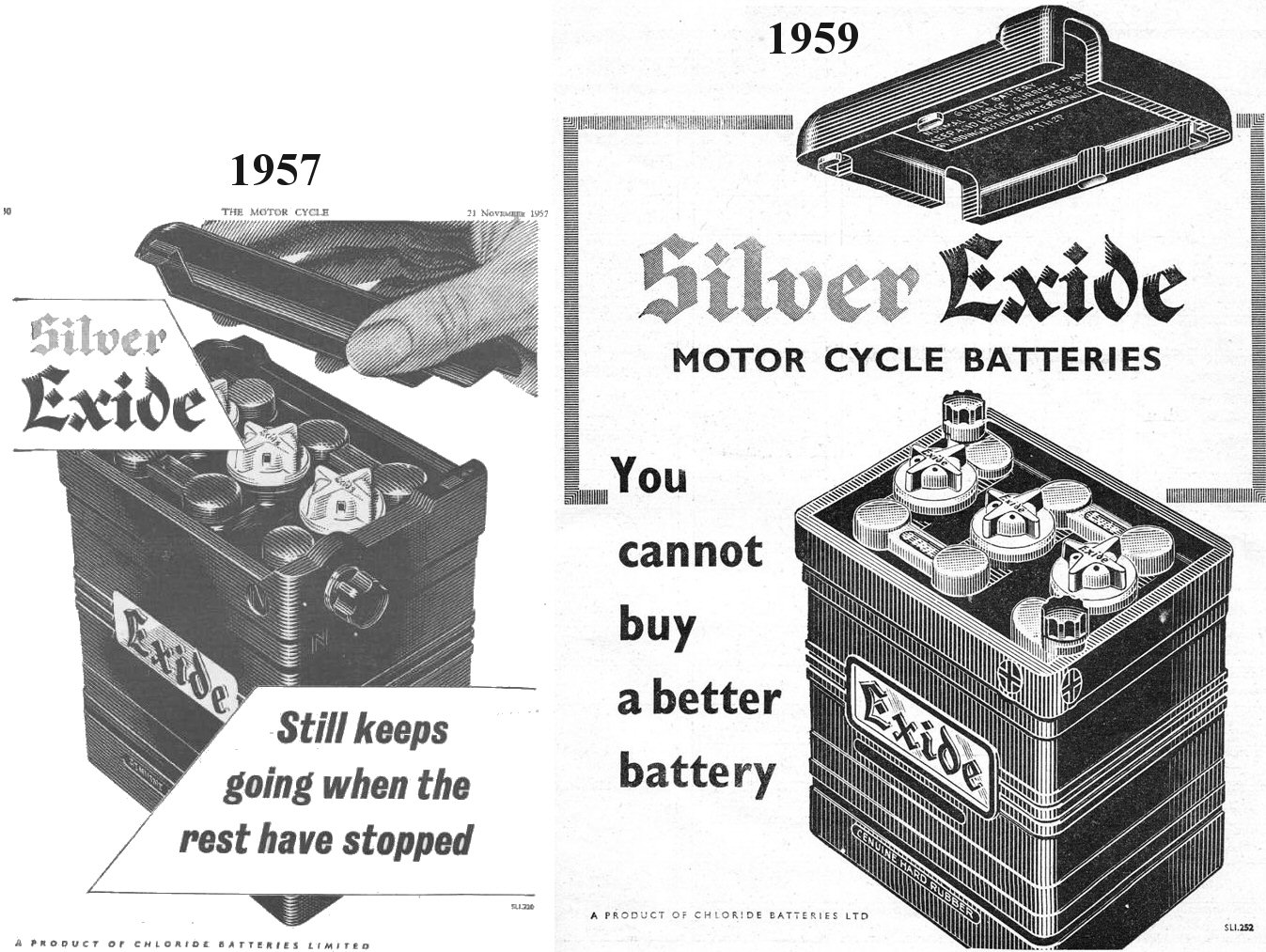
1957 and
1959 Chloride Batteries LTD - Exide battery ads
I have always wondered why the empty battery case
supplied by restoration suppliers did not seem to match
the 1947-1955 era period Vincent photos. After searching
thru 1950's era Exide motorcycle battery ads it looks
like the case design was changed in 1958 or 1959.
So now we know this empty Exide case we purchase to look
like a period battery is indeed an Exide motorcycle
battery design, simply late 1950's. If anyone has
further info please dont hesitate to contact me. I know
the earlier Exide had a variety of Bakelite post knobs,
some hex nut shaped, some large round knurled, some as
shown.
It would be nice to have some period documentation on
the colors used on the Exide battery case logo
|

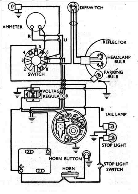
The first (upper) diagram shows the insertion of a Podtronics
rectifier/regulator and an 12 volt Alton generator.
It is a bit more detailed than the diagram below, showing all
the connectors, wire colors and additional ground points.
This diagram shows a redundant - closed loop ground wiring
system. This is intended to reduce dependency on the frame for
ground purposes in the charging circuit.
The second (lower) diagram is as the bike was built using the
12 volt Alton generator and an Alton supplied
rectifier/regulator. It is a bare bones diagram.
I installed a key switch to correct the small electrical
bleed off problem with leaving the battery connected for longer
periods of time.
Within 2 years, the Alton supplied rectifier/regulator
failed, and Paul Hamon recommended using a replacement. I
selected a Podtronics unit as installed in the upper diagram
(Marc Michel TT Restorations)

Discussion of modern Voltage
Regulators:
I installed the Alton unit and I find there is a 23mA bleed to
ground through the voltage regulator green ground lead. The
Vincent 12v battery was running down when simply sitting and the
fault traced to this. What is my problem? Craig
Comontofski 11/7/2011
On the wiring diagram ("magneto" type) we suggest to add a switch to
avoid a small leak current passing through the small black wire of
rectifying regulator when the bike is at rest. This is
approximately 20 milliamps. Not very high but enough to
drain a battery in a couple of days (depending on the battery
range). So add this switch if you want to avoid this
problem. Another solution is to remove the fuse as soon as
your bike is at rest for more than a couple of days. Or
alternatively to use a home battery charger for long
rests. This inconvenience comes from the source
of rectifying-regulators. They actually come from small
capacity Japanese motorcycles on which the ignition key
switches the small black wire of rectifying-regulator (as
indicated on the other diagram). In this case no leaking
current because the battery is disconnected from the
rectifying-regulator when the bike is at rest (ignition off).
If you start the bike without switching "on" and run the generator
with "open" circuit, it is not so good for both generator
and rectifying-regulator if you insist for all trip but it
won't destroy them for just a couple of minutes running this
way. By the way if you do so you surely can hear the generator
"rumbling" and of course the needle of ammeter won't move at
all. Paul Hamon 11/8/2011
Voltage regulators for DC generators have a requirement to isolate
the battery from the generator's armature when the armature is not
rotating. Failure to do so would put a load of around 1/2 Ohm (the
resistance of the armature winding) on the battery. Mechanical
regulators use a relay. Leakage of relays is so low measuring it
would be counting single electrons. Solid state regulators
typically use a diode. All diodes have a leakage current
specification. The leakage can be measured without substantial
heroics which is to say it is in the milliampere to microampere
range. Solid state regulators for alternators use Zenor diodes to
turn thyristors (SCRs) on. SCRs are just three of four (depending
on how you like to count them) diodes in a fancy configuration.
But we are back to diodes, things that leak. The diode can be
specified to minimize leakage but at the price of compromising
another specification. The design of a regulator (and just about
anything else more complicated than a paper clip) is an exercise
in compromise. There is no Utopia. Sorry, limitations of available
technology. Doug Wood 11/9/2011
Series "D" Vincent Distributor:
40455A dist service 40455/S clockwise turn 16-18 degrees DKX2A
Weights assy= 415729 ,
contact breaker complete = 400164
points = 400415 ,
cond = 400308 ,
cap = 400136 ,
springs = 421457/S
Jim Wilson 11/10/2011
NGK B6ES spark plug equivalents: NGK 7432,
Accel 143, AC Delco 43XL, Autolite 2616, Beck Arnley
176-5002, Bosch W8CC, Champion N5C, Champion 120, Denso
W20ES-U, Denso 3051, GM 5613104, Mighty M4G3, Motorcraft
AG3CX, Prestolite 14G3, Splitfire SF405F. Bill
Babcock 8/30/10
U.S. spec Miller headlight shell on that
machine which originally took a GE 3044 sealed beam
headlight. Peter Guldan 8/17/10
For the best 6 volt battery at the best price
try the toy section at wal-mart. The 6volt battery they sell
to power the vehicles the kids ride in is actually a good battery
and the most inexpensive I've encountered, besides being the
right size for the dummy battery box. Bob Bonato
8/17/10
PODtronics regulator:
- RED wire of the regulator to the
ammeter
- BLACK wire of the regulator to earth
- YELLOW wire of the regulator to the D
terminal of the generator
- GREEN wire of the regulator to the F
terminal of the generator
Your should also insert a fuse before the
ammeter. I use 15 Amp. If your battery if heavily
discharged when you first commission the system you may blow the
fuse if you turn the headlight on. Actually it is an
inexpensive and meaningful test that I have run
accidentally. Assuming I built the generator (or at least
it was wired as I would have), to motor the generator:
- temporarily connect the F terminal
to earth
- temporarily connect the D terminal
to +V
The armature should rotate smoothly
clockwise as viewed from the drive end. Doug
Wood 5/14/10
So far there has been three electric starters for Vincents. Both Grosset and Conway starters
operate through the gearbox mainshaft and the primary drive. Both
these are more safely operated with the help of the valve lifter
or a decompressor, particularly if there is a chance of a
kick-back or if you have a very high compression ratio or radical
cams. Bob Dunn's version (also seen on Dick Craven's Prince)
drives the crankshaft directly and appears to be immune to such
phenomena. But its not as pretty. I always use
the valve lifter (Conway starter) but there have been occasions
when I forgot. That's ok with a warm engine but otherwise the load
will hammer any battery (up to 16Ah) into low voltage at which
point the starter solenoid tends to drop out. Eddie
3/7/10
Altette Horn
Manual: http://www.britishonly.com/pdf/lucas/sectionL7partA.pdf
10/3/09 http://www.bolsover.com/lucas/sectionL7partA.pdf
8/21/10
To test
your Miller D6 first
determine which of the four wires are the field coil and which
are the resistor. To do so measure the resistance between
all pairs. If you measure two wires not connected, i.e.
one from the resistor and one from the field coil you will
measure a very high resistance. The resistance coil will measure
two to three time higher than the field coil. The
resistance coil can be ignored for the moment. Pair a field coil
wire with a brush. Don't stress over which wire or which
brush. Pair the remaining field wire with the other
brush. Connect the two pair to a battery. It does
not take much thought to realize that the armature, the field
coil and the battery are now all in parallel. The generator
should now motor. It should motor smoothly. If it
does not motor smoothly something is wrong and should be
addressed.
If the armature rotates CW as viewed from
the drive end then you guessed correctly. If not swap the
field wires and try again. Now take you volt meter and connect
it in place of your battery. Drive the armature CW and
your generator should create a voltage. If not something
is wrong and needs to be addressed.
If the generator passed all tests is
basically works and you can consider wiring it as a Lucas or as
a Miller. Doug Wood 5/29/09
Miller dynamos, as originally wired, work differently then
Lucas. Millers have three states of operation:
1. Output voltage is too low
2. Output voltage is about correct
3. Output voltage is excessively high.
In the first state the armature voltage is
impressed directly across the field coil. Assuming that
the cut-out relay is closed this would also put the battery
across the field coil. If the voltage is low enough then
the battery will be disconnected (as in start up
conditions). This will maximize the current flowing
through the field coil, implying a maximized magnetic field.
In the second state, where the system has
equilibrated (sort of), the current through the field coil is
decreased but not to zero. There is a resistor that is
inserted in the field coil circuit. The resistor, which is
the second winding on the field coil (wound non-inductively) is
the mechanism for decreasing the field coil current.
The third state has no current flowing
through the field coil. Without this current there can be
little or no output voltage.
While this system sounds good, in practice
it barely works. It is a fragile design that typically has
been abandoned for the simplier Lucas type voltage control
(states 1 and 3 only). I am not aware of any solid state
regulators that will support the Miller regulation design,
This is not to say that they could be designed but rather that
there would be little demand for them. Based on that
assessment I would hazard a guess that your 30 year design would
require rewiring the Miller.
FWIW I will not rebuild a dynamo in the
Miller configuration as I do not trust the reliability of the
regulation system.
Doug Wood 5/28/09
Even if properly polarized,
if you're not providing 6V/12V
power to field coils when
testing ouput on the bench .... or a lathe, then output is very
negligible, like less than a volt at lower rpm. To put
it in perspective, most mechanical regulators excite (switching on
power to the field coils to begin charging) at only .50 volts -
and a POD at .75 volt - generator output as the generator is
only using residual magnetism within the field coils at that point
to produce anything. Peter 5/27/09
Alton 2 phase 12
volt battery: Yuasa BZ14. 14 amp hour 12
volt battery, as recommended by Francois Grosset for his electric
starter. It fits the standard carrier without modification.
Old Lucas Booklet:
All about Dynamos: http://www.motos-anglaises.com/catalogues/magazine/motor-cycle/dynamos.pdf
Bruce Metcalf
Gel Battery:
This one costs a bit more but it fits very nicely and puts out 14
Amp hours which is unusually high for a small 6 V . Size is 2
3/4 x 4 3/16 x 5 1/2. Called the dealers and the price was
$29 2 years ago.
http://www.parmakusa.com/Additional/parts.htm Mike Hebb
4/12/09
Gel Battery:
http://www.voltmanbatteries.com/servlet/the-53/SLA0975%2C%C2%A06-VOLT-14-AMP/Detail#itemadded
6volt,
14
amp.
Check
the
dimensions. Mike Hebb 12/12/09
WESTCO 6 Volt Gel Battery
see:
http://www.westcobattery.com/battery_page.php?bid=59&vid=-1
6.5'' and 7.0'' HELLA headlamp complete w/ a parking bulb that Fits our Miller headlamp shells. All @
$19.00
Store Name: PUMA Store
Address:1670 Enterprise Pkwy.Unit E
Twinsburg ,Ohio 44087 USA
Phone: (800) 354-
3552
330-425-2800
Fax: 330-425-2818
Email:info@puma-access.com
http://www.puma-access.com/index.php?main_page=product_info&cPath=9&products_id=287&zenid=85370e6e350b5ffe572ff792b5d725c2
General sources of 6 and 12volt Halogen
headlight bulbs:
http://www.startright.co.uk/index.php?main_page=product_info&cPath=145_285_286&products_id=8662&zenid=4edbbd43957c80bbd25d3f9c04e551f4
http://www.nextag.com/h4-halogen-bulb-6-volt/products-html
http://store.candlepower.com/bconah4ha60b.html
http://www.flandersco.com/action.lasso?-search&-database=_Flan_Levers.fp5&-layout=Electrical&-Format=ElectricalResults.html&-Error=ElectricalError.html&-Operator=Contains&Electrical%20Photo%20Prefix=G
http://www.bikebandit.com/product/A4557898
http://www.yamaha-xt500.com/newshop/index.php?productID=101
Also, JC Whitney has them in 55/60W. Part
number is ZX304576F.
Carl and John 12/1/08
Hella headlight unit: Q. Are these "right hand dip" US
style, or do they, er, swing both ways the way Cibie units
did? A. For UK applications use the repro unit
designed for the Honda CB250N Superdream. It drops straight in and
takes the H4 P43T standard bulbs. Neil Diggins 12/1/08
6 Volt sealed
battery:
http://www.westcobattery.com/battery_page.php?bid=59&vid=-1
Headlight: I used a Honda V45, 1982-83 headlight
#33120-MF5-751. It comes as a unit. You break the glass chisel out
the caulking and re-install the unit into your Miller shell. It
accepts a 65W quartz halogen bulb. With the Miller lense in
place you can't tell what kind of reflector is used. Franc
Trento at franc@eurobrit.com.au is reproducing precise replicas of
the Miller lense. Carl Hungness 9/4/07
Headlight: I am pretty sure that a HELA #70003 light unit
will fit a 6.5 inch rim. John Mead 9/4/07
Bosch GL9 Points =
1951-57 Reliant Bosch GL98 Condenser =1953
P24 Plymouth- Sunbeam-Vauxhall Velox
These are the correct points and condenser for
the Vincent Distributor (DKX2A). They are readily available in any Auto
shop in Australia. Greg 6/18/07
Dynamo Checking:
Let us assume that you want negative earth as Vincents (certainly
with a 3-1/2" dynamo) should have. Also I will assume that the
dynamo is off the bike. If you position the dynamo so the
commutator end is toward you and the armature at the 12:00 position
the brush on the left side should be the ground brush and the brush
on the right the positive. Additionally there are two field
coil wires coming from the bowels of the dynamo, one of which may or
may not have an ientifying tag. Small matter. Temporarily
connect one field coil wire (doesn't matter which one) to the ground
brush and the other to the positive brush. Now connect the
battery to the dynamo, actually now a motor, one battery terminal to
each brush, negative to the earth brush.
If the armature rotates clockwise viewed from the drive end we
have the field coil hooked up correctly. Otherwise reverse
the field coil wires and repeat. It is necessary to get the
dynamo to motor in the correct direction to ensure the field pole
shoe is properly polarized.
Now comes the time to connect the regulator. In general
there are two types of which I know: high side switching and low
side switching. What does that mean?
The dynamo output voltage is limited by switching field coil on
and off. Output voltage too high? Disconect the field
coil. Output voltage too low? Reconnect the
field coil. Only one side of the coil is disconnected.
PODtronics and (I believe) Bell regulators switch the low
(negative) side of the field coil. This is true irrespective
of positive or negative earth. I cannot say with certainy
anything about the switching of the JG or K-Tec units.
There are at least two 4BA screws coming through the brush
plate. One of them may be common to the positive brush
(it is when I rebuild a Miller). It is worth checking with
your Ohm meter. The other is probably just a tie point for a
field coil wire. Check for (lack of) continuity to
everything. Doug Wood 6/1/07
Relays & Switches: It’s
surprising how much you can get into the headlight shell. In mine,
I’ve got a couple of automotive-type relays each wrapped in
rolled-up strip of foam rubber so that they end up 1-5/8” dia. x
2-7/8” long. The fit in to either side of the ammeter.
One of mine is a latching relay (e.g.
http://www.autoelectricsupplies.co.uk/product/178 ), and the relays
are rigged up so that only a single thin wire goes to a simple
push-button switch on the handlebars. When the headlamp’s switched
off, the push-button acts as a flasher (using both headlamp
filaments), and when the headlamp’s switched on, the headlamp
toggles between main and dip with each press of the pushbutton. My
ammeter has a white plastic translucent case, and as a main beam
tell-tale, I’ve got a couple of LEDs mounted on a tiny piece of
Veroboard on the ammeter fixing studs so that the ammeter glows
green when on dip, and blue when on main beam (and also of course so
I can see the ammeter reading in the dark). I’m
running a 6V Altette horn on 12V, so I’m not worried about voltage
drops in the horn wiring, and I don’t keep my finger for ages on the
horn button, so I use a similar thin wire between the headlamp shell
and horn button.
I’ve made a replacement for the throttle twistgrip body with a
homemade switch built into it for the horn. On the left-hand side,
I’ve got a symmetrical lump of stainless which (i) acts as the
clip for the valve lifter main bracket and (ii) houses the
dip/flasher switch. The two thin wires run in a length of
heatshrink from the headlamp shell to the underside of the
handlebars between the handlebar mounting clips, where they go
through a little hole and then run in opposite directions inside
the handlebars and come out through little holes next to my lumps
of stainless. All in all, it results in very uncluttered
handlebars, with the clutch and valve-lifter levers and the horn
and dip/flasher switches nicely placed.
The other nice feature is that the stop has broken in the Miller
light switch, which fortuitously provides an extra position in
which only the pilot bulb is on, so that can be used as a daytime
running light without wasting precious Millertricity on the tail
and speedo bulbs. I think I’ve got one of Goffy’s
(NORBSA02@aol.com) 23 W halogen bulbs
(http://www.norbsa02.freeuk.com/goffybulbs.htm) in there as the
pilot bulb. Ken 5/26/07
Wiring Harness: Boating
suppliers
like
West
Marine
carry
wire, sometimes referred to as "boat cable" or "boat wire". that is
much superior to the bare copper sold in auto parts stores. It has
finer, tinned strands, so it is more flexible and corrosion
resistant than the auto store stuff, and easier to
solder. Steve Lindbloom 5/25/07
Battery Ground:
This all imprtant connection is relegated usually to the common thin
wire held against the side of the oil tank, usually a high
resistance affair. Use a heavier wire with a
suitable eyelet bolted to one of the studs holding left side
plate FT 5 . If an electric starter is fitted this
grounding becomes even more critical. On the
Vincati we use a heavy ground cable from the battery post
sourced from a big Jap bike - the size of your
little finger. All ground wires possible connect
to a heavy common cable and also bolt to this
plate. All lights are brillant and the Alton
worked powerfully from day one. The battery stays
up beautifully too. We run twin in line
fuses - one for the general system, another for the starter 's
solenoid circuit. A key switch shuts off All
power after it passes through the fuse, then supplies these two
systems. Thus there is no drain nor hot wires with the keyed
switch { beyond the switch } turned
off. Sid 5/25/07
Modern Lights:
A
good
headlight
replacement
is
the HELLA unit. The glass cut is very good for driving, directing
the light where it needs to go. The glass sticks out from the rim
about a 1/16''. There are two sizes and not to worry about the ''T''
clip 6 1/2'' headlight shell/ rim, one of these two will fit.
contact: PUMA or Preformance
Unlimited
30700 Bainbridge Rd
Unit L
Solon
Ohio
44139
Telephone 440 498 0638. Fax. 440498 9647 (new address/phone
1/19/02)
The ''T'' Clip headlight unit takes #70003, or
hella #1A6 003 402 812 12V unit 154 The cost is about
$33.00 +/- bucks.
The 7'' split rim headlight takes # 70476 @ about $ 42.00+/-
bucks
Run a modern quartz-halogen headlight bulb an H4 of
amy voltage, any wattage and the nice thing about these are, they
have a parking bulb (nobody I know leaves a light on when
parking), already built in. For those states or
countries that require a 'lights on' driving situation, don't
touch the actual glass of the bulb. JS Wilson 9/26/01
Lucas Generator Parts Misc:
Generator - Lucas 20013
Armature - 200304, E3HM-LO 1946-47
Commutator end bracket - 200270 or 200269
Drive end bracket - 200353
Field coil - 200188
Through fixing bolts - 200227
Band cover - 200609
Brush set - 200290
Brush spring set - 200079
Brush gear (insulating plate) - 200431
Commutator end cover - 200354
Shaft nut - 170104
Bearing bush, Commutator end - 200231
Drive end bearing - 189307
Sundry parts kit - 249683
Jim Baltusnik 7/4/06
Lucas Distributor Parts Misc:
Series "D" Vincent - DKX2A
Bearing bush - 420406
Distributor base - 400001
Rotor arm - 400052 (not sure of this number)
Condenser - 400136
Shaft and action plate -
Coil - model LA-6 volt ignition coil, Part No.
45076
Contact breaker -
Distributor cam -
Clip cover retaining - 410591 or 420261
Lucas Magneto Parts Misc: (for "C" Shadow
and Rapide): (for extensive
Magneto information please see the Magneto Tech Section)
KVF GM1 42134
Contact Breaker Cover: 458647
Contact Set: 470877
Contact Breaker End Plate: 458633
Armature: 458679
Cam Ring: 458661
Contact Breaker Springs: 470688
Spring and Pin in CB COver: 458613
Slip Ring: 454497
Auto Advance: 47505
My '54 Rapide has what I
think is the usual four-position Miller
switch marked:
"Off",
"Ch" (which is still off),
"H" (head, tail and speedo)
and
"L" (pilot, tail and
speedo).
If you are unfortunate enough to break off the
bakelite stop inside the switch, you'll find you aren't so
unfortunate after all. You get a fifth position, and then a repeat
of the same five positions with the other end of the knob pointing
at the markings. The extra (unmarked) position gives you pilot
only, without speedo and tail, which is great for daytime running
especially with a bright little halogen bulb for the pilot.
If you want to go a stage further, you can swap the dipswitch and
pilot light connections to the switch. The "H" and "L" markings on
the switch are then the wrong way round, but the fifth position
then gives you head, again without tail and speedo. Ken
Targett 7/16/06
Battery: All other batteries I've run into sort of fit and
put out 6 to 10 Amp-hours. This one fits very nicely and
puts out 14 Amp hours. Size is 2 3/4 x 4 3/16 x 5 1/2.
Called the dealers and the price was $29. See
http://www.parmakusa.com/Additional/parts.htm if
intersted. Mike Hebb 6/18/06
Headlight
wiring: when fastening
wires to the Lucas brass connectors in the headlight switch or
horn..... always hold the connector with a small open end wrench
against the tourque of your screwdriver.... this will prevent the
connector from tearing loose by breaking the plastic or compressed
insulation material used on the horn.(You have disconnected the
battery- haven't you?) Rip Tragle 4/26/06
Marchal headlight
bulbs for Miller 6 1/2" Vincent Headlights: I
stock 6V 35/35W Quartz halogen Marchal headlight bulbs. These
are a direct replacement for the original and a lot brighter.
They are £12.00 ea. ($21.00). I also stock 6V 10W & 20W
quartz halogen pilot bulbs in both 9MM ad 15MM bases. these
are ideal for a daytime riding light. £4.00 ea ($7.00) Post to
US 2/3 days £2.00 ($3.50) Visit my website
www.norbsa02.freeuk.com Paul Goff 3/26/06
Headlights: A fine replacement for the stock Vincent reflector
can be had by obtaining a 1982-83 V-45 Honda reflector. It fits
into the Miller 7" assembly perfectly and of course accepts the
quartz halogen bulb assemblies. Carl Hungness 3/23/06
Kubota alternator (15531 64010) and regulator
(19267 64602) can be adapted for Vincents.
McDouglator
Technical Article by Carl Hungness
RB 107 Lucas Regulator info:
http://www.britishonly.com/pdf/lucas/sectionL3partB.pdf
Vincent headlights were in three configurations to the States. Early
had the 8". Later came with the 6 1/2" which utilized a
bulb. Also common in the States (and France) was the sealed
beam headlight. (Lucas 400
series 7 inch) These had
a different rim that was split at the bottom. It also had a
locating notch at the 11 o'clock position for the sealed beam
unit. These are really two different components. The most
distinctive thing about the Miller headlight utilized (by Vincent)
was the triangulated boss on each side where the bolts screw in. I
don't think that Vincent used the 7" version which has no boss but
then I'm not sure. I don't think that Phil Vincent would
come running into the assembly line shouting " Shut down the
production line, Miller can't supply the proper 61/2 units
and we can't have concours judges arguing 50 years from
now." Velocettes also used them as well as the 7" units. To
confuse things more, when Harpers took over both, if you ordered a
headlight, they would send a 7" unit with a Vincent wiring
harness. Not that any of this mattered, they were all connected to
Miller generators. Somer 1/1/05
A Vincent does not have a 7 inch headlamp
Shell- that is Velocette. Vincent headlamp is 6.5 inch
nominally. (The lamp does not vary in size [but nothing
surprises] however 7 " lenses Were sometimes fitted with a
big rim for the USA market. With a tape measure, measure the
arcate (accurate ?) length of the bit that sticks through
the rim ...6.5 inches or it's just under 6.5 inches at the widest
point.. with a ruler. OK replicas of the 6.5 inch unit are now
available from a Velocette guy (ironically) in UK who makes them
in India. The glass is not right but OK. Arthur
1/1/05
Podtronics manufacturers two entirely
different types of voltage
regulators.
#1 For AC alternators. Turns AC into regulated DC.
Creates heat in the process. This is a rectifier-regulator.
#2. For DC generators. This is a true regulator and controls
output by modulating the field current. They generate a
small amount of heat as a by product.
The above mentioned #1 regulator is intended for AC alternators
such as used on late BSA, Norton & Triumph. Also used
on Alton, which is an AC alternator. This
regulator-rectifier turns the AC into regulated DC, and turns
excess electrical energy into heat. Do NOT cut off
fins. Do NOT mount in enclosed space. Do NOT mount in
Miller box.
#2 The second Podtronics regulator is a DC regulator
intended to be used on DC generators (dynamos) such as those used
on 50's (and earlier) BSA, Norton, Triumph, and Vincent using
either Miller or Lucas generators. These are very efficient and
yes, they CAN be mounted inside of the old mechanical Lucas and
Miller regulators. There is a small amount of heat generated
as a by product, but is of no consequence. (All components
inside this regulator are certified up to 125 degrees C.) We
have done bench testing using a fibreglas replia Miller box with
no problems after an hour of running time.
Bob Kizer 12/11/03
Great list of sources for Generator and
Magneto repair:
http://www.1bigred.com/blancard/Resources.html
jim 11/11/03
Ignition Advance: Blued pipes occur as a result of idling and
running with the ignnition firing point being held too long
too near TDC. The result is burning being sustained too far
down the power stroke, actually a plume of flame extends out the
exhaust port and down the pipe for about 8 inches - more or
less. In fact mixture correctness can be judged by the
flame's color. Extreme top end heat and oil
temperature results as the cooling fins are unable to dissapate
the added heat. Sid Biberman 7/8/03
Waking up a
Generator: In order for the generator to start
spontaneously there needs to be some residual magnetism in the field
coil shoe or less likely the generator body itself. The shoe
is made of (I believe) soft iron and as such has fairly low magnetic
retentivity. So you have to "flash" your field on occassion.
Flashing the field forces a curent to flow through the field winding
creating the attendant magnetic. The domains in the field shoe
align and remain so when the field is removed. This is
the afore mentioned residual magnetic field.
How to flash your field? Assuming you have a negative earth
system and a Bell regulator, try temporarily connecting your
armature output (possibly labeled "D" or if color coded a yellow
wire) to the + terminal of your battery. This will bypass
the "cutout" diode in your regulator. Then momentarily (<
one second) connect your field output (labeled "F" or perhaps a
green wire) to ground. Your field is now flashed.
Disconnect all temperary connections and reconnect permanent
connections. Doug Wood 4/21/03
Headlight bulbs: The six volt is a "Stanley" brand, # A6867 .
6V30/24W. You should be able to order a box of 10 from a good Auto
parts source. The side lamp is a 6V bayonet base flash light (four
cell) bulb. If you think the bike will be used in the dark, I'd
highly recommend that you contact Bill Easter for a Quartz lamp
conversion. John 6/24/02
Armature Failure: If you have positive charge when lights are not
on, then it sounds as if your headlight is drawing an excessive
amount of current.
1. Try installing a standard 25/35 watt
headlight bulb (25 watt low beam) and see if that makes a
difference.
2. Check to make sure that both high and
low beam filaments are not on at the same time. This will
put a tremendous load on the dynamo.
3. Make sure you have a seperate ground
wire running from battery chassis earth to headlight earth.
Bob Kizer 4/21/02
Armature Failure:
In all my years of refurbishing dynamos, the usual cause for shorted
turns, open turns, or shorts to the core is because the owner
expected too much of a device which was made cheap. Often the
regulator was set too high so that the overall charging rate
exceeded 10 amperes plus the two amperes required for the field
winding, thus causing the windings to overheat or the solder to get
thrown out of the commutator. Rewound armatures with modern
insulation and being dynamically balanced can go a long way toward
improving reliability. Perrry Gerhart 4/21/02
Battery Technical
Site: http://www.largiader.com/articles/battery.html ( updated 8/30/10 )
Amateur's Guide to Horn
Restoration: I've stripped and
repaired several horns and there's not much to them. They contains
a coil, and set of points and a diaphragm. The points are in
series with the coil and when they open, the coil's magnetic field
collapses. They are so positioned that when current enters the
horn the coil pulls the diaphragm inwards and opens the
points which collapses the field which releases the
diaphragm which closes the points and gives us magnetism
again and again and again... .
My steps are:
1. Disassemble - You shouldn't have to open
the big nut in the middle of the Diaphragm but open everything
else.
2. Clean any spider nests and rust out of
the inside.
3. Check the current path for opens or
shorts.
4. Clean the points and all screwed
connectors to bare metal.
5. Clean and oil all threads.
6. Check coil for continuity. If it is bad,
give up and get it rewound or find another horn. If
you don't have a meter, briefly apply voltage through the coil
and see if you get magnetism.
7. Make sure the adjusting screw on the back
really does change the point gap when turned and the spring
works.
8. Reassemble and test. Use adjuster on the
back to adjust the horn tone and volume. If it makes just one
pop of the diaphragm when you try it, the points are not opening
when the diaphragm pulls in. If it makes no noise, then the
points are open when current is initially applied and they
should start out closed.
9. When you get some noise, turn the
adjusting screw till the sound stops in both directions and pick
the best tone in between.
Be especially careful where wires attach to
the back. If they are open and can get wet, it can short from
the connection to the horn body and cook all your wiring. On the
Vincent the horn wire is always hot and it's activated by
providing a ground path with the switch. An inline fuse is
advisable.
10. Polish, paint, rechrome or whatever you
like to the outside and you're in business.
Mike Hebb 3/9/02
Vincent Twin Electric
Starter: (Note: a complete set of Vincent installation
instructions is available
here.)
Four different designs of slip clutch and
electric motor were tested during the development of the Vincent
electric starter. The Mark IV version has been selected after a
test period of 1000 starts which consisted of 50 starts per day
for three weeks.
An 1100 Watt starter motor,located under the
gearbox,is mounted on a special “G50” alloy pivot plate and is
quite inconspicuous. The power is transmitted to the gearbox
mainshaft via a reduction gear (400 RPM at crankshaft). A
specially designed slip clutch is used to disconnect the starter
motor when the engine is fired. The original kickstarter remains
operational;
G46 rachet pinion needs an easy modification
with a lathe. A 12 volt 12 amp/hour jelly battery fits into the
original battery carrier.(Yuasa YTX 14BS), only a longer anchor
stud and modified clamp strap are needed. The extra weight
to the machine is approximately three kilos.
No alteration to the crankcase is
necessary. A slot must be machined into the kickstart cover.
This modification is reversible. Should you wish to return to
the original design, weld a piece of alloy to fill in the
machined slot. The conversion is delivered as a kit including
all the necessary parts exept the battery which is available
from any modern bike shop.The kickstart cover and rachet pinion
may be sent to the address below and will be returned ‘ready to
fit’ with all the parts.The assembly can be done by any good
Vincent enthusiast mechanic in a standard workshop.
Price : 1400 Euros the
complete kit with a second hand checked starter motor,
available
for
positive
earthed
machine
only.
1500
Euros
the
same
complete
kit with a brand new starter motor,
available
for
any
positive
or
negative earthed machine.
Prices
do
not
include
postage
or shipping charges.
Contact: Francois Grosset, Le Pont Ricoul,
35720 St Pierre de Plesguen, France.
FAX: 33-299-73-94
17
E-mail: pontricoul@aol.com
KVF Vincent Magneto Trivia
KVF dated 3/46 P403K, C225
On one side of the mag body, up by the flange, is cast P403K.
180 degrees out, on the other side of the magneto is *stamped*
LT7277
Stamped coaxial with the armature, mid body, left side viewed
from drive end.
H84 stamped coaxial with armature, mid body, top.
Both mags have the letter U stamped on the
bottom, close to the
mounting flange.
KVF dated 1/51 P403K, H84
KVF dated 3/48 P403K
KVF dated 12/51 P403K cast in circular logo
1/2"dia. jim
Modern Lights: A good headlight replacement is the HELLA
unit. The glass cut is very good for driving, directing the light
where it needs to go. The glass sticks out from the rim about a
1/16''. There are two sizes and not to worry about the ''T'' clip
6 1/2'' headlight shell/ rim, one of these two will fit.
contact: PUMA
or Preformance Unlimited
30700 Bainbridge Rd
Unit L
Solon
Ohio
44139
Telephone 440 498 0638. Fax. 440498
9647 (new address/phone 1/19/02)
The ''T'' Clip headlight unit takes
#70003, or hella #1A6 003 402 812 12V
unit 154 The cost is about $33.00 +/- bucks.
The 7'' split rim headlight takes #
70476 @ about $ 42.00+/- bucks
Run a modern quartz-halogen headlight
bulb an H4 of amy voltage, any wattage and the nice thing
about these are, they have a parking bulb (nobody I know leaves
a light on when parking), already built in.
For those states or countries that require a 'lights on' driving
situation, don't touch the actual glass of the bulb. JS
Wilson 9/26/01
Testing your Armature: One side of the condensor should be
unsoldered. I would recommend the side opposite the HT
turret on the slip ring. Primary (low tension) resistance as
measured from the amrature core to the wires that you just
unsoldered shuld be approximately 0.5 Ohms. Secondary (high
tension) resistance measured from armature core to slip ring brass
should be 5000 - 5500 Ohms. Doug Wood 06/24/01
Polarity: With everything connected up just depress the
cutout contact for a few seconds. This will direct charge
from the battery around the field windings and re-magnetise the
field magnets with the correct polarity.
Battery: Walridge Mtrs list a 6 volt black rubber original
style ( p.94/2000 cat. p/n 14075 2 $105.82 cdn). Also listed
is black rubber shell with lid similar to original 6volt battery
(p/n 99-920 $47.96 cdn). They also state they can supply 6
or 12v battery to fit inside case, no price or p/n given. They can
be reached at E-mail: walridge@gtn.net or Phone: 519 641
2770 or FAX: 519 473
3960 John Cousens 05/06/01
I thought that I would put
the facts on the table as to the
development of the Alton.
This started back in , I think 1989, when I
was seen by Herve Hamon with a Kubota alternator in my hand at
an Annual Rally ( Fort Purbrook, Portsmouth). Herve went home to
France, and having, at that time some paternity leave
French, you know) for a year. A lot of spare time on his hands (
after putting Ettiene in the crib in the workshop, they train
them the right way in France!) Work was then done in
producing some prototypes, using several different methods of
drive ,and speeds. When it was found to be successful, but
lacking in as much that it could only be used on twins, due to
the large diameter of the rotor, it was decided to manufacture
one of three inches diameter, so that it could be used on
all machines that used a Miller or Lucas dynamo.
The initial prototype parts were made by
me, including the tooling for blanking out the segments for the
stator( soft iron) Much time was spent between here
(Hayling Island ) and Auray on the southern coast of Brittany.
Unfortunately One of the early prototypes was seen on a French
bike by a British journalist, and publicity was given , long
before any real development had been carried out. I was flooded
out with enquiries from all over the World. This was something I
did not need, having a business to run , sometimes 50 calls in a
single day, and me not being able to give a sensible answer.
Nowadays most of the parts are made in France, with only some
gears made locally here in Portchester.I do not have any
involvement in the project
now.
This is where I will disagree with the
statement made that the magnetic pulsation's of the Kubota, are
the cause of taking out the rollers on the primary chain. If a
Kubota is held in the hand and given a quick twist of the wrist
it will spin easily, until it slows down enough for the magnets
to take over again . So when the alternator is running this
effect makes no impression . What does happen is that there is a
far greater load, than what was developed by the original
dynamo. Bikes that have a Fiat or Bosch automobile dynamo have
also been known to shed their rollers. It`s the increased
load that is the problem. That and poorly maintained chains ,
running far too slack. Getting the sprocket in the right
place , central to the links , and with a good clearance above
the rollers, helps. A plastic sprocket is being
experimented with to see if it is a going concern.
Trevor 04/30/01
The rearlight wiring runs up one leg and the stop light wiring up the
other. Also if you look under the rear hinge, you will find
grooves milled out for the wire to pass under this component and
then onto the rear/stop light assembly. D.J.P. 04/27/01
Do-it-yourself magneto: The ordinary multimeter applies only a few volts
across the terminals.
Use a megohmmeter with 500 volts
applied. 1000 megohms is a reasonable value. The
capacitor needs to be disconnected from the coil. Test hot
at 180F. Test the coil for leakage, same way. Test
the isolated coil for passive voltage with the 200 millivolt
scale on an ordinary multimeter. The higher the voltage(5
to 50 millivolts) the more water is is the coil. Bake
it out for day or two at 180F( post
bake voltage should be less than 10 microvolts) and recoat with
coil varnish.
Encourage Doug Wood and Bob Kizer to write
a manual for these tests, defects, and cures. Perry
Gerhart 03/31/01
<<Did you use a megaohm
meter on the mag to verify that the condenser is working as it
should? This is the only way
to accurately check a mag condenser.>>
Yes, a megaohn meter will act as a
capacitor tester as it will judge the ability to take on and
hold a charge. (as does a capacitor tester) I"ve tested hundreds
of Lucas capacitors and haven't found a "good" one yet.
They are all leaky to one degree or another. Even if you
find an NOS one still in the box, it will test leaky.
Lucas was ahead of their time in manufacturing biodegradable
parts. (the capacitors used paper dialectric) Bob
Kizer 03/31/01
Along with people, magnetos
and paper dielectric capacitors suffer from old age. A 50 year old magneto
has outlived it's usefulness. To use a "band aid" approach
is to only prolong the inevitable. Overhaul it correctly,
rewind the armature, use a good quality capacitor suitable for
pulse application, and you probably won't have to do it again for
another 50 years.
Bob Kizer 03/31/01
There have been a multitude
of discussions, in print, about how
to time your Vincent over the
years and I have done my level best to research many of
them.
The "poke your spoke"
method of inserting something into the cylinder surely leaves
much to be desired as far as accuracy goes. Moving the engine
5-l0 degrees is actually VERY little.
Once again we refer to
"40 Years On" where methods ranging from dial indicators to
putting a bit of soap over the plug hole (and watching the
bubble rise or fall) to give us Top Dead Center.
No matter how you find
TDC, it is a simple enough circumstance to install a degree
wheel and check yourself. Then simply make up a spark plug stop
(again see the method in 40 years On..whereby you bust up an old
plug, thread a bolt into it, and set it precisely at TDC)
I have utilized my spark
plug stop guage a couple of dozen times to re-time my bike and
am "chuffed like a parrot" to say more often than not she has
started first kick after installing the mag.
Once again, the
installation of the mag, figuring out precisely where the points
open, is covered in the "40 Years On" but to summarize, you take
out the center bolt, hook up a small dash style light, watch it
go on and off..and you 'll know precisely when the points
break.The do break electronically a bit faster than visually...I
know many have used cigarette paper and a "feel" method..which
works well too.
Measuring this spark
plug angle is, yes, like measuring with a mike and cutting with
an axe.I love that analogy..and had forgotten it.
` Remember to block
open the ATD when setting the mag...
I know from experience
this procedure can be done on the road..and I feel confident the
measuring down the hole method has started many a Vin over the
years as well. My point is, make the spark plug stop, carry it
with you and you'll never have to worry about where 38 or 39
degrees is again. Carl
Hungness 03/30/01
Here is a technical tip for
all you Vin/Ariel members that have ammeters with the red jewel in it. I modified Rob Arnott's ammeter by
drilling a .099" hole in the back and gluing a super bright red
LED into the hole with superglue. The LED was connected in
series with a resistor and the resulting illumination was very
impressive with only 20 milliamperes
going through the LED when the ignition was
switched on. Polarity of the LED needs to be observed.
The Vincent had negative ground so I connected one end of the
resistor to the anode, positive, longer lead of the LED, and the
other end to the connection on the ammeter lamp socket with the
white wire on it that goes to the ignition switch. The
shorter lead on
the LED was connected to the ammeter lamp
socket with the yellow wire on it that goes to the dynamo
armature. This can be used for either 6 or 12 volt
systems. I used a 510 ohm, ½ watt resistor for Rob's 12 volt
system. A 240 ohm, ¼ watt or larger resistor can be used on
a 6 volt system. Bill Easter 03/15/01
I had run a Mistral/Lucas
Rita setup for a few years, (once I'd sorted out a
reliable power supply) and it ran very well but,
1) It sucks a lot of power, like almost 4 amps on 12 volts. 2) I
wanted to hide the coils under the Mag cowl and used small twincoils
which would go about 3000 miles and just die. Burn them out, even
expensive Dyna coils, although they did not measure the 3 ohms that
they were stamped with. I didn't want the 2 big old Lucas coi;ls
hanging out in the air so paid the price in coils.
I then switched to HD stuff fitted to the Mistral housing which I
still run. Dan Smith started this, now many local bikes run it,
and John McDougall has been making housings to suit. The benefits
are many. Two stage advance curves operated by a vacuum switch.
Low power draw. Parts available very readily. You can tuck it all
under the mag cowl. There are for those who like to fiddle with
that sort of stuff, programmable boxes that you can program more
stuff than you'll ever need. Do you need to have nitrous
arming and firing points? How about if you have and
electric start you can program the engine to turn over a
designated number of turns before it fires to avoid backfiring on
start up. Robert Watson 03/09/01
Engineer Kirby Rowbotham builds the Boyer Bransden "Micro-Digital" system
into his own replica magneto housing, for mounting in the standard
Vin magneto position, all for £320 (GBP320). These run with
the miniature "digital" coils supplied, to allow two-plugs-per head
firing. I think he advertises in CB, CBG etc. magazines.
His system is claimed to have independent (i.e. per-cylinder)
EEPROM-based adjustability of timing curve. Phil
Blakeney 03/09/01
Does anyone know if you can run a dyno without a battery. I
think you need the battery to excite the field coils to get the
armature to produce current or will this happen when the dyno begins
to spin? John Mead
Hello John, It depends upon what regulator you are
using. If you are using the original Lucas mechanical, there
is no problem.
The voltage to excite the field actually comes from the generator
armature and is switched on and off by the regulator. (this is how
they regulate maximum voltage) If you are using K-tec,
then the answer is no. Because the K-tec uses a Darlington
transistor for field switching, which requires 1.4 volts to
initialize, they use battery voltage to excite the
field. On the other hand, if you are using the
PODtronics DC regulator, there is no problem as it will operate
very nicely without a battery in circuit. (and it fits
inside the mechanical regulator box) Bob Kizer
02/27/01
I have been using a 12V Alton
alternator on my 'C' Shadow for a couple of years
with absolutely no trouble at all. It just always works and I
would recommend one. I find the "break-even" point to run my
quartz headlight, instrument lights, and high wattage running light
to be about 50 mph in top gear--that's fairly low rpm and certainly
the wrong gear for that speed. Its output is claimed to peak
at 150 watts sustantially more than any 6V DC generator.
I tested prototypes for ALTON. My findings were that
electrically it was just fine right from the start and once they
got into production any minor mechanical problems had all
disappeared. It's a nicely built piece of equipment and is a
direct replacement for the original Miller unit except it is 12V.
BTW...I run magneto ignition--no particular reason except it has
never failed me. It does have an advantage if I leave
something on and run the battery dead. Jay Schaffer
02/13/01
A Dynamo is a machine that when driven by a prime
mover, such as a water turbine or a Vincent, is called a
Generator. It changes mechanical
energy to electrical energy. If a Dynamo is supplied electricity and
it's output used
to supply power to mechanical devices it is called a motor.
Generators are rated as to the Watts they can supply at a rated
Voltage and Speed without Overheating. Motors are rated to the
Horsepower they can deliver at a given Speed and Voltage without
Overheating. Now Forget motors! This is about Generators!!
There are several ways to control the Wattage: (One) Speed
Control, that's the thing your right hand does. (Two) voltage
control. That's the thing the regulator does to the field windings
of the Generator. There are two ways that you as a Vincent rider
will deal with hooking up the field to the voltage controller.
(One) in Series with the Armature; (Two) in parallel, or
Shunting, The Armature. You can hookup any Miller, Lucas, Bosch or
Chinamo to do either. JG units are hooked series, or externally
grounded, K-Tec, Lucas regulators are hooked Parallel or,
internally grounded. By looking at the drawings in KTB,
Richardson, diagrams that were supplied with your regulator or, by
looking in an old Auto repair manual you'll be able to see these
differences. Since all these Generators were made to run in
motorcycles you can see the speed part of their rating can be
anywhere from less than two thousand to over seven thousand RPM!
If they are not overheating they are safe, so go ahead and spin
the generator a little faster, it won't bother it a bit. One
Hundred-Twenty watts at twelve volts is still in the working range
of Your Sixty watt, Six volt Generator. John 12/20/00
Looking at the diagram by JG, it appears that the
gen is wired in shunt. I believe that the JG unit varies the
current through the field to regulate the output. It is a
parallel generator. John 12/20/00
Dynamo: I fitted a good condition E3L generator, only
modified in the wiring as explained by JG, and a 12 volt JG
regulator to my "D" Comet some years ago. The instructions with
the regulator said that it would produce 12 volts with
approximately double the output. This is what it has done
without any troubles, until I removed it about two months ago.
However, a later modification on this side
of the pond is to fit the distributor from a car and have 12
volts with an out put of 15amps or more. One of the favourites
is the generator from a Citroen 2CV, due to it's small
size. As I have plans to update my lighting and possibly
fit an electric starter, I have fitted a car generator to
the Comet. Of course there is much more room to fit it on
the Comet, so I have fitted a slightly larger generator that has
the rectifier pack and the regulator mounted under
the end cap. This is driven from a
small dummy dynamo incorporating a pulley at the non-drive end
which in turn drives the alternator with a poli-V belt.
The finished results have been very impressive, with the
alternator balancing the load of every item on the bike at a
fast tick-over. Derek Peters 12/20/00
When Joseph Lucas designed
the dc dynamo, he did so with neither an excess of steel nor
copper. Of course, it depends upon what size wire is used in
the 12v rewinding. When going to 12 volts, less current will
be required to do the same amount of work. In order to get
higher voltage (at lower rpm) the wire must be smaller so
that more wire can be wound on the armature. And of course,
smaller wire has more resistance, thus increasing the I^2*R
(current squared times resistance). So yes, all things being
equal, you still have a 60 watt instrument. However,
by using a 6-to-12 volt conversion regulator, you can use that 60
watt headlight whilst utilizing that 6 volt armature. The
only "problem" is that you must spin it faster to get that full
12v output.
If you use a JG converter or similar you
can use a 60/55 watt headlight bulb bulb. The converter will (or
should) protect your delicate little field coil from harm by
limiting its current. At 12 volts, the field coil might
draw as much as 6 amps. Bob Kizer 12/14/00
Both a generator and an alternator do the same thing: convert mechanical energy
(rotation) and magnetic energy (either a permanent magnet or a
field winding) to electrical energy. As Mr. Kizer so
correctly stated: "There's no such thing as a free lunch."
If you want to get 60 Watts out of a generator you need to put 60
Watts into it...plus energy for all the losses.
If you are simply trying to run a 6 Volt
generator at 12 Volts exercise caution: the field coil will have
the full 12 Volts impressed across it. Since resistive power
increases with the *square* of voltage (all else being equal)
your poor filed coil will be asked to dissipate *four times* the
energy it was designed for. So generally the voltage
across the field coil is limited to 6 Volts. The easiest
way to do so is with a series resistor. But this may not
be the most efficient.
The situation with the armature may not be
so bad. Again, assuming the desire is to run a 6 Volt
generator at 12 Volts the load (lighting, field coil,
accessories, etc) may be specified such that the current
requirements may actually decrease (a primary advantage of
higher Voltage systems). In this case a 6 Volt armature
may work... but at the price of requiring higher RPM.
My take on this situation is:
1. A 45 Watt bulb puts out just about
45 Watts wether it is 6 Volt or 12.
2. All things being equal 12 Volt
systems require less current, therefore are more forgiving of
sub-optimal electrical connections.
3. There is an upper limit on what
you can get out of a 35 Watt generator.
4. There is no upper limit on what
you can put into a 35 Watt generator, short term.
5. It is my opinion that if you want
a 12 Volt system you should convert to 12 volt components (field
coil, armature).
Doug Wood 12/14/00
The generator/dynamo
has two essential parts, the armature and the field coil. These
can be configured in one of two different ways. 1) Armature and
field coil in parallel with each other, and having a common ground
(earth). This is the arrangement as shipped from the Lucas factory
and utilizing the old fashioned Lucas mechanical regulator.
2) Armature and field coil in series
with one brush connection earthed, and the other brush sharing the
"D" terminal with one of the field coil wires. This
arrangement is required for some solid state regulators such as
the JG. Although there are some solid
state regulators that require condition #1.
You can flash the field for one of
two reasons, or both. 1) To reverse the polarity or
2) To restore residual magnetism. In this situation,
we are doing it to increase the residual. Remember, the
mechanical regulators can initialize with as little as 0.1
volt. But due to the characteristic of
silicon solid state devices, they must have in excess of
0.7 volts. This can be accomplished by either
flashing the field, or spinning the armature faster and
faster. The residual magnetism decreases with time.
If the bike hasn't been ridden in several months, it's possible
this will restore the lighting.
The Miller (and Lucas) should have two
outlet termainals. One should be marked "F", and the other
marked "D". The green wire from JG should go to the F
(field). The "D" terminal will most likely have blue or
yellow. I'm betting that flashing the field
will restore operation, but if it doesn't, you might want to
consider the PODtronics. They are designed to be more
efficient and
therefore consume less power, thus
generating less heat. And they're small enough to fit nicely
inside the Miller and Lucas boxes. And yes, the "hot"
terminal is the one that isn't earthed. Bob Kizer
12/14/00
Maybe all open "D's" were fitted with the
Lucas model 564 tail light, but the enclosed models were fitted with model
529. You need to ensure also that you get the right model
529, which is 53429A, as they were also made without a
connection for the Stop lamp. Derek Peters 12/14/00
Regulators: At one time JG was availabe epoxy potted
inside of the owners Miller box lid. It's my understanding
that this feature is no longer available and can only guess it was
because of insufficient heat sinking. (These generate about ten
watts of heat at full output.) Keep in mind that
each time the bike is started, the generator creates output
voltage using the residual magnetism from the last time it ran.
Also, keep in mind the poles of the generator are soft iron and
will not stay magnetized indefinetely. The "drawback" of
solid state regulators is that they require approx. 0.7 volts to
initialize. If most of the field
magnetism is lost, the regulator will not
initialize. But the fix is simple. (please note this applies
only to generators wired according to JG instructions)
1. Disconect the regulator from the
generator (US generator = UK dynamo)
2. Run short jumper wire from "F" to
ground.
3. Attach wire to hot terminal of
battery.
4. Briefly touch other end of this wire
to "D" terminal on generator.
5. You have now "flashed" the field.
6. Disconnect the jumper wires and
reconnect the regulator.
Bob Kizer 12/06/00
While we do have some very knowledgeable and able
craftsmen rebuilding both magnetos
and dynamos who advertise in
the VOC MPH journal, I wish to recommend a couple here stateside
whose names and addresses seem to be fairly secret.
I have had excellent experience with a magneto
rebuilt by Bill Jean 757 488-7l9l of Virginia (Sid Biberman's
partner in the restoration field) and Rip Tragle revamped my
Miller generator to l2 volts and after 20,000 miles seems to be
working great...Tragle is of course a journeyman engine rebuilder
as well..his phone is 9l4 676-3304.
Nevertheless, after some
correspondence with Mark Goodson I am pretty well convinced that
the Chinamo he discovered is well worth looking into..it
generates a very healthy output, and is reasonably priced.
Available from the VOC Spares company. The main problem with the
generating system, my research has shown, is not the generator
itself, but the regulator. And nowadays we have our choices of
several modern ones that seem to handle the load with
consistency
Personally, I love the idea of being able
to start the bike and drive it home, without a battery.
Then again, after doing considerable damage to my knee last
summer I am looking forward to the day I can afford an electric
starter..but I'll still keep the magneto. Carl
Hungness 9/'29/00
How to fit an electronic
ignition unit to a Comet.
I can only refer to suppliers etc. in the U.K. Here most of
the conversions seem to use Boyer Bransden units. Kirby
Rowbottom using a Boyer Bransden unit can convert a standard
magneto to contain the sensor unit, which consists of a magnetic
rotor and a stator plate and then the only other component is a
transistorised control box about the size of a twenty pack of
cigarettes. The only item not included is a standard
coil. Most of them are powered by 12 volts and I would
recommend a conversion. I used a standard Lucas E3L dynamo
and a "JG" voltage conversion unit - this converts the standard
dynamo to 12 volts while doubling the output to 120 watts.
If you have machining facilities I consider the way I did it to be
the best solution. I machined an alloy casing rather like a
distributor and mounted it in the same way as the "D" distributor
so that it can be turned to obtain that final timing
adjustment. This unit had two small bearings, a 1/2 " shaft
and a cavity to contain the rotor and stator. It is driven
by a standard tufnel gear. I dealt directly with Boyer
Bransden, who I found to be most helpful. Initially they
recommended a unit made for the Triumph &BSA
Singles. However, when I mounted it on the bike there was
insufficient advance to allow correct timing for both running and
starting. I phoned their technical department and they asked
me to return the control box. Within a few days back
came a new box bearing the inscription -"HIGH POWER IGNITION UNIT
- SPECIAL: VINCENT COMET - WIDE ADVANCE". Needless to say it
has functioned perfectly ever since.
This advice applies equally to
Twins. Derek Peters
9/29/00
Altette Horn Repair
Issac Lynn "Taff the Horn"
20 the Glebe
Bishopston, Swansea,
West Glamorgan SA3 3JP
South Wales, UK
lynn.isaac@tinyworld.co.uk
Lynn (known as Taff) Isaacs is a ruddy miracle
man on all types of horn. Has 9000 horns and specs on almost every one ever
made. Got me one for my 37 Rudge Ulster, rebuilt my A and the C
(12V conversion). Hardly ever uses pattern stuff (re wiring is
new!!) and charges are embarrassingly modest. (Authur)
7/18/00
Return to:
thevincent.com