
Vincent
Technical Sections: -Serial
Numbers/Production- Photo Gallery of
Models - Brakes
- Engine
Overhaul - Vincent
Engines - Wheels/Fenders
- Instruments
- Transmission
- Clutch - Magneto - Tank/Seat - Suspension
- Tools - Norvin -
Electrics-
Carburetors -
Misc - Links -Vincent
Parts/Services Suppliers - Polishing/Cleaning
- Shipping Vincents-Electric
Starter - Paint/Transfers
 Overhauling
the
post war Vincent power unit - Service Data on this famous
Thoroughbred
Overhauling
the
post war Vincent power unit - Service Data on this famous
Thoroughbred
The Vincent motorcycle engine is
designed to give long periods of service without major attention,
and whilst the handbook gives instructions for decarbonizing it does
not cover more extensive overhauls. The following notes are intended
for those who have the necessary mechanical aptitude to undertake
the job themselves and familiarity with the general details of the
engine thru study of the instruction book is assumed.
Fitting
Crankshaft to Engine
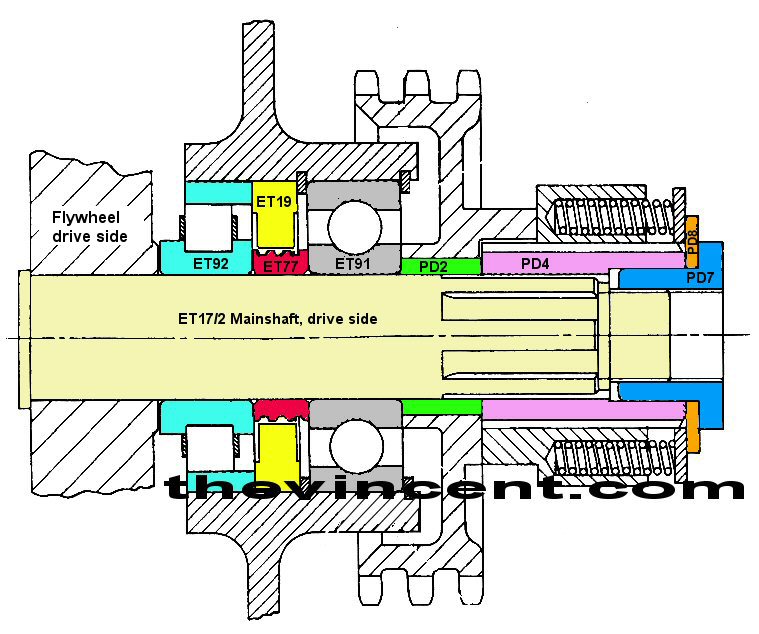
Centering the crankshaft in the Vincent engine cases is an important
part of the reassembly process. The stack distance of ET92, ET77,
ET91 determine the position of the left flywheel and ultimately the
position of the rods in their cylinders. The position of the inner
most roller bearings (ET92) is critical on both sides. The clearance
on ET92 is tight, but the rollers must fully engage their outer
races on both sides. There appears to be several thicknesses of ET77
used over the years of Vincent engine assembly, most likely having
to do with the roller bearing thicknesses of the time. Shims are
available to insert between the bearings and the flywheels to
achieve rod centrality, however with a too thick ET77, it would
appear reducing the thickness will be required.

Cylinder
Head and Barrel
The earlier type kit spanner for the push rod tube gland nuts was
not always strong enough, but the prongs of the current pattern
spanner will shift these nuts even if they are very tight. If the
stainless steel tubes are difficult to lower in the synthetic rubber
glands a smear of oil will help, and if the jaws of suitable pliers
are wrapped in a rag the tubes will not be marked. The cause for
frequent need for adjustment on one tappet should be investigated;
it may be that undue loads are imposed on the valve operating
mechanism by a coil bound valve spring or a valve stem collar
hitting the lower valve guide. Rockers which have more than .010"
sideplay in the bearing should be shimmed up as otherwise the inside
of the fork will foul the valve stem (fig 2 ).
Both fork ends should bear evenly on the stem collar, and if
necessary the higher fork end can be carefully stoned down.
Clearance of the bearing in the head is up to .002" when new, but as
the bearing is surrounded by oil slightly greater play is not
detrimental. Bearings are now available in .002" oversize, but
fitting may require skimming the tunnel; usually a new standard size
bearing restores the clearance to normal. A worn rocker bearing is
unlikely to fail suddenly and renewal is mainly advisable on account
of mechanical silence. Metering wires are recommended for all rocker
feed bolts, but the bearing lubrication can be increased by fitting
a thinner wire than standard.
Valve Clearance
Clearance of the valves in the lower guides is
important; .002-.003" is recommended for inlet and .003-.004" for
exhaust. Normally renewal is recommended when wear exceeds .003",
depending upon operating conditions. For removal of the lockrings
the tool shown in figure 3 is used and when dealing with the actual guide
the head is heated up to 200 deg C. Valve springs are renewed when
they have settled down to 2 1/16". Seat rings seldom require
replacement, but they cannot be removed by heat; worn rings are
carefully broken up by drilling or turned out in a lathe.Grinding
stones dressed to 30 deg are used recutting.
Piston
Clearances
When new, piston clearances are as shown in Fig. 4, but while no
hard and fast rules are laid down as to relinering and reboring,
it is frequently accepted that wear in the top of the liner must
not exceed .008in., but earlier attention is necessary if a liner
is badly scored or worn oval. Oversize pistons are
available, but it is much better to fit Service Exchange barrels
which are relinered to standard. The same applies when
high-compression pistons arre installed for using premier grade
fuels. Piston ring gap is .016in-.020in. compression and
.010in-.020in scraper and, whilst a larger gap does not matter,
rings eventually lose their strength, so that renewal is usually
advisable. The gudgeon pin must be an easy push fit in the piston
when cold and new pistons must be installed the right way around,
i.e., with the larger cutaway facing the inlet valve. When
fitting genuine replacement high compression pistons it is not
necessary to rebalance the engine. Clearances are
comparatively low and progressive running in for at least 2,000
miles is essential.
Timing Gear, Primary Drive
The plunger of the lubrication system presure
relief valve must be an easy sliding fit in the timing cover,
otherwise it may stick in the open position. This reduces
the flow of oil to the big end and premature failure will
eventually follow. If oil restrictor discs are used to
reduce the lubrication of the cylinder wall these discs are fitted
behind the rear rubber washer of each pair inside the timing
cover. All timing gears are fully marked, but when dismantling
note the position of various thrust washers (Fig. 5). The
idler gear is mounted on an adjustable boss for resetting to zero
backlash against each cam pinion, and oversize half-time pinions
in steps of .002in are available for use when idler gear
adjustment gives too much clearance on the half-time pinion. Cam
followers always show signs of wear in service, and if the grooves
worn across the component are not more than 1/8in wide the
follower can be refaced on an oilstone. Badly worn followers
can be built up and reground locally, but renewal is probrably
easier. A small ridge on a cam indicates that the follower
is not tracking correctly. The ridge can be stoned off and
the follower is lined up by adjusting the thickness of the thrust
washers.
Replacement camshafts are normally
only supplied complete with pinion; the assembly is not keyed
and pressing out the old camshaft may affect the required
interference fit. In any case a jig is required to obtain
the correct relation of the cam relative to the markings on the
pinion. Timing gear spindles are inserted after the case
has been heated up to 200 deg. C., and if a spindle is found to
be loose it can often be plated up to the required oversize and
refitted after the case has been heated locally with a blow
lamp. A big end roller is peened into each exhaust lifter
and this roller may come adrift if the exhaust lifter has been
used at too high r.p.m. It can be repeened into position
if the lifter arm has not worn, otherwise a new arm is required.
Primary Chain
The primary chain requires renewal when
stretched more than 1/4in. per foot, and usually this is indicated
by all external adjustment having been taken up. As fracture
of the chain may cause irreparable damage to the drive-side
crankcase it is a wise precaution to renew every 20,000 miles on
account of the great power output of the 1,000 c.c. engine.
The component is endless and removed together with the sprockets (Fig 6).
Spare parts for the triplex chain are not supplied. The
tensioner blade always shows grooves, but replacement is called
for when these grooves have worn half-way through the
component. A cracked blade must be renewed without delay.
The chain features straight links for use with a tensioner and
only genuine replacements may be fitted.
The shock absorber nut has a right-hand
thread and must be dead tight. Considerable leverage is
neccessry if the tool kit socket spanner is used for removal or
tightening, and it is permissable to lock the primary drive with
a wooden or soft metal sprag. A loose nut affects the
location of the flywheel assembly and causes spring fracture;
springs will also break when the shock absorber cam is badly
worn. It is advisable to renew the complete cluster of
springs and reassembling the shock absorber is greatly
facilitated by partly withdrawing the splined cam sleeve rather
than trying to compress the spring cluster by hand!
Crankcase and Flywheel
Assembly
On the twins the crankcase halves are retained
by sixteen bolts and studs and there are three hollow dowels for
alignment. Jointing compound is used on the faces.
Splitting the halves to remove the flywheel assembly necessitates
withdrawal of the half-time pinion with the extractor illustrated,
but the remainder of the timing gear, magneto, oil pump and filter
can be left in position if desired. The matched cases are
made from a low-silicon alloy which can be welded provided care is
taken to avoid distortion.
Bearing races are fitted after the case has
been warmed to 200 deg. C., preferably in an oven, and the
crankcase metal is then staked as shown in Fig.7.
Races which are loose in their bores, but otherwise in good
condition, can be plated up to the required oversize provided no
plating solution comes in contact with the bearing track.
The required interference fit is .002in.; if more the race will
contract to such an extent that the runnung clearance is
reduced. An interference fit of .001in for the spindles in
the timimg side case is sufficient. Spindle bores which
have been worn out of round due to loose spindles as mentioned
above can be bored oversize to take stepped spindles which will
have to be made up. Oil leaks past crankcase bolts are
avoided by fitting with some jointing compound, and this also
applies to the cylinder holding down bolts. Sometimes the
rear bolts break through into the cylinder feed gallery from
which oil under pressure may work past the threads. Make
sure that these bolts do not pass oil by fitting with some
jointing compound without blocking the cylinder feed.
Poorly fitted holding-down bolts cause oil to accumulate in the
tunnels of the alloy cylinder jacket which eventually shows up
as a leak from the front of the barrel below the head joint.
Big End Renewal
Big end renewal is not necessary before
up-and-down play exceeds .003in, and crankpin wear by the
seperators is not detrimental provided the roller tracks are in
good condition. Inspecting or renewing the big end is,
however, a works or specialists's job, and the component parts are
not supplied loose. Oversize rollers are not available and
the conrod sleeves are ground after pressing into the rod.
The works supply a completely assembled big end fitted to
reconditioned service rods. Clearance of the gudgeon pin in
the small end bush is .001in., and the fitting of a new bush is
not beyond the scope of the private owner provided he remembers to
drill the oil holes and possesses a 7/8in. reamer. Side
clearance of a big end, felt at the small end bush, is not
detrimental.
The flywheel assembly is located from the
drive side without being affected by the shock absorber springs;
no percepable end float is permissable, and .010in. shims are
sometimes used on the drive side of a Black Shadow to obtain
perfect centrality of the small end bushes in the cylinder
registers. Inner bearing races which are a slack fit on
the mainshafts will turn and wear the flywheel boss away.
If this has happened the worn boss can be turned off and
substituted by a hardened shim.
Owing to their generous dimensions main
bearing wear is very low; renewal is necessary when up-and-own
play exceeds .0015in. or when a bearing feels rough if spun by
hand. It is surprising how a little roughness in one main
bearing may render an engine noisy. When reassembling note
that each roller race is refitted to its own outer ring.
Lubrication System and
Clutch
The condition of the teeth on the oilpump
plunger can be observed without dismantling the pump; excessive
wear on these teeth indicates that the pump has beeb overloaded,
possibly due to an obstruction oin one of the oilways. If
the plunger requires renewal the oilpump sleeve must be replaced
as well, as these matched components are supplied only in
pairs. Use a ring spanner to unscrew the oilpump cap and a
stout screwdriver to remove the locating screw, which is normally
punchlocked. The plunger is tapped 1/4in B.S.F. for
withdrawal and the top end of the pump sleeve 5/16in. B.S.F.; to
extract the latter part a crankcase bolt can be used, but it is
necessary to dismantle the driveworm first. Earlier oilpump
worms were made from bronze, and if these are worn it is better to
fit the current steel pattern. Wear on the actual pump is
usually very low, and provided the drive parts are in good
condition it is rarely necessary to withdraw the sleeve.
When reassembling use jointing compound on the cap as well as on
the locating screw, as air leaks here reduce the scavenge
capacity. With banjo washers in good condition there is no
need to tighten the light alloy banjo bolts to the point of
fracture.
The fitting of a new oil filter element is
advisable and all external pipes must be clear with the rubber
hose in good condition. If the earlier type inspection-cap
spanner does not fit the filter chamber cap the outer periphery
of the tool can be ground down without detriment to allow for
slight variations in crankcase castings. Damage to the
taper of the chain oiler calls for replacement of the screw,
which is a standard Amal carburetter component. Swilling
the oiltank with degreasing fluid will release sludge from the
trap at the rear, and as the stop valve gauze is surrounded by a
shroud this job cannot be done with the tank in position.
The big-end quill must be scrupulously cleaned; signs of slight
rubbing of the quill in the timing side mainshaft do not matter
provided the quill is not weakened.
Clutch Lifting Mechanism
Normally, only slight wear takes place in the
clutch lifting mechanism, and the standard length of the pushrod
is 12 5/16in. If worn prematurely the rod can be divided, hardened
where cut, and refitted with a 1/4in. dia steel ball in the
middle. When cutting the rod make due allowance for any wear
which has already taken place, as well as for the diameter of the
ball. A worn lever can be built up with the Stellite or
similiar process if no replacement is available. Clutch
linings must be free from oil and the seals in good condition.
Duron moulded linings which are groved (see Fig.8) may
powder to some extent. They may be washed in clean petrol,
roughed up and the grooves scraped out. A new bonded carrier
seal is always necessary and if not readily available a hard
copper washer of the same thickness and o.d. makes a good
substitute. The leading clutch shoe-lining edges must be
well chamfered to avoid fierceness in operation and steel plates
which show signs of distortion should be refaced on a surface
plate. Clutch shoes which are badly worn on the pivot holes cause
judder rather reminiscent of a chain jumping a sprocket in bottom
gear. If rebushing is not possible the shoe must be renewed.
Gearbox and
500c.c Models: Final Instructions
It is rarely necessary to dismantle the
gearbox to cure jumping out of gear; trouble of the nature can
nearly always be rectified by careful adjustment of the selector
mechanism, the fitting of the later type pawl carrier centralizer,
one-piece footchange lever or new selector pawl spring. The
box must be dismantled, however, to split the crankcase, although
new oilseals can be fitted without disturbing the internals.
Both seals are identical, of the spring-loaded synthetic rubber
pattern and fitted with the spring and the lip facing
inwards. Access to the gearbox is gained by removal of the
clutch, primary drive, dynamo and kickstart cover. This
exposes on the left-hand side the gearbox cover plate (Fig. 9) and on the
right-hand side the kickstarter ratchet parts are pulled off the
shaft after removal of the Seeger circlip. After unscrewing
the eight retaining setscreews (locked by tab washers) the cover
plate is released by a tap with a copper mallet on the right-hand
end of the clutch shaft. The plate is then withdrawn
complete with shaft and constant mesh pinion and this exposed the
other gears which are still retained by teh camplate
spindle. A large screwdriver is neededto unscrew this part
(usually punchlocked) from the top of the driveside crankcase and
it is tapped 1/4in. B.S.W. to facilitate final withdrawal. The
gearbox internals can now be taken out with the exception of the
final drive shaft; the third gear pinion can be examined in situ.
Rounding of the dog clutch teeth does not
matter so long as the gear changing is not affected, but gears
with badly pitted or chipped teeth must be replaced. Side
clearance of the selector forks should not exceed.010in. and
selector pins should be renewed or turned in the forks when they
have worn flats more than .005in. deep. A camplate must be
renewed when clearance between the slots and selector pins
exceeds .020in., backlash on the bevels can be taken up by
shimming.
For reassembly the gear cluster is put
together on the bench with the double gear to the right and the
large pinion away from the operator. On the layshaft the
order of assembly by the number of teeth on each of the four
gears is 29, 23, 18, and 27, the two middle gears being embraced
by the grooved selector fork. The camplate is placed on the
selector forks with the bottom gear notch in line with the
selector bar and nearest to the assembler and the cluster
entered into the gearbox shell. Check the indicator lever
is back in bottom gear position before the camplate is fully
pushed inwards, refit the camplate spindle and complete the
reassembly of the box in the reversed order of dismantling.
With the exception of the gearbox,
practically all the foregoing is equally applicable to the
500c.c. machine. The idler gear drives the dynamo on which
the pinion is tapped for withdrawal with the extractor shown in Fig. 10.
Note that on 500c.c. models the slot in the breather spindle
does not face forwards, but downwards. The single-row
primary chain has a spring link, but the shock absorber is
identical to the one used on 1,000c.c. models; there is,
however, a spacer behind the sprocket.
return to thevincent.com