
Vincent
Technical
Sections: -Serial
Numbers/Production-
Photo Gallery of Models - Brakes
- Engine
Overhaul - Vincent
Engines - Wheels/Fenders
- Instruments -
Transmission
- Clutch - Magneto
- Tank/Seat - Suspension
-
Tools - Norvin
-
Electrics-
Carburetors
- Misc - Links
-Vincent
Parts/Services Suppliers - Polishing/Cleaning
- Shipping Vincents-Electric
Starter - Paint/Transfers
Vincent
Transmission
-
One, Two, Three, Four
Transmission
Restoration, V Twin
All B, C, and D twin transmissions were basically the
same.
However, from 1946 to 1955, minor weak points in the
original concept
were discovered. The right hand crankcase casting was
modified in the
transmission area, in that additional meat was added for
greater
support of the shifter cam spindle and the shifter shaft
support
area. The cam plate shifter quadrant received a
support band
around the shifter shaft coupler tongs. The shifter
pawl
adjusting plate received over shift stop gears. The
Lightnings,
if ordered, had a higher low gear ratio than the standard
pedestrian
twins, G9/1 had 21 teeth, G11/3 had 27 teeth, that would be
the double
gear. The Shadow and Lightning shifter cam plate can
be
identified by a series of quarter inch lightening
holes. The
transmission counter shaft sprockets can be identified in
the following
manner. A road model sprocket is solid, except some
Shadows, not
all, were drilled for lightening, and had 21 teeth, giving
an overall
delivered gear ratio of 3.50 to 1. Lightnings were
thinner, to
accept the 520 chain drilled for lightening, and had 22
teeth.
Most Lightnings left the factory with an overall gear ratio
of 3.27 to
1. During the Korean war, some metals weren't
available.
Transmission gears suffered during this era, with low grade
gears. These gears can be identified by their number,
352.
Vincent transmission gears that are identified by
designation number
such as EN36 are of better quality, much
stronger.
If the motorcycle is in running order, it's a good idea to
take it
around the block a couple of times prior to tear down and
restoration,
to determine the preliminary condition of the
transmission.
Finding out how it shifts, and finding any obvious defects,
like
jumping out of gear, or excessive noise emanating from the
transmission
area, could be helpful later on.
Start your tear down by swinging the rear brake pedal
assembly out of
the way of the primary. Place the bike on the rear
stand.
Swing the front stands into position to achieve a four point
support
for the machine. Remove the clutch derby. Place
a drain pan
under the transmission area. Remove the drain plug
from the
primary chain cavity. Now go to the right side and
remove the
transmission drain plug, found forward of the transmission
shift cover
in the right hand crankcase side. The drain pan should
have a
capacity of four quarts. Now remove the clutch
assembly.
Inspect the area directly below the now visible primary
cover seal. If
dry and free from excessive oil, the replacement of the seal
probably
won't be necessary. When there's no drip from the
primary drain
plug, you can remove the primary chain cover. Inspect
the primary
seal again. It should be soft and flexible to the
touch, with no
hardness and no visible cracks to the rubber seal
portion. If the
seal appears suspect in any way, replace it.
You can now remove the primary chain clutch sprocket and the
crankshaft
sprocket. Inspect the retaining bolts of the
transmission
door. They should be drilled and safety wired.
Often
they're not. The reason for the safety wire necessity
is the fact
that the door receives a twisting torque caused by the lay
shaft gear
cluster trying to climb the main shaft cluster during
acceleration and
deceleration. The visible hex head cam plate indent
plunger and
spring assembly must be safety wired as well. The
twisting torque
has a tendency to loosen the retaining bolts, and loosen the
aligning
dowel in the bottom circumference of the transmission
door. Next
inspect the transmission's main shaft end clearance.
This is
easily done by taking the exposed main shaft and moving it
athortship
back and forth. The end clearance shouldn't exceed
.007. If
.007 is exceeded, write down in your tear down reference
notes, the
amount of shimming required to achieve a .005 to .007 end
float.
You can now go to the right side and remove the exhaust
pipes.
Remove the adjusting screw on the transmission shifter
cover.
Remove the clutch cable access cover. Unhook the
clutch cable
from the clutch release arm. Remove the clutch cable
from it's
clutch cable housing stop bore. Place cable out of the
way.
Shift transmission into neutral. Remove shift lever,
kick start
lever, and transmission gear indicator arm.
As the transmission shifter cam plate spindle is under the
battery
tray, it's necessary to remove items in order to gain
access.
Remove battery, battery strap, and the battery tray support
bolt.
You can now swing the battery tray up and out of the
way. Swing
the right hand foot peg assembly up and out of the
way.
Place a pair of vise grips on the shaft of the gear selector
positioning pointer. Feel for any slack or backlash
between the
shifter cam plate bevel gear and the bevel tooth
quadrant. You're
testing for excessive gear wear, and improper fitting of
parts.
The proper mesh of the bevel gear and cam gear is important
for a
nicely shifting transmission. Often the shaft
alignment through
the transmission cover is out of align, causing friction
between the
shaft and the outer cover, which every time causes an ill
shifting
transmission. This is especially true when using a
cover from
another engine, or a reproduction cover.
You can now remove outer transmission shifter cover.
Remove
kicker quadrant, inner shifter arm, and shifter pawl
assembly.
Leave the adjustable stop tab in place. Before removal
of the
adjustable pivot for the inner shifter arm, scribe it's
adjusted
position around the two washers. The pot metal slotted pivot
pin
support scribes easily. When the transmission is
reassembled,
this gives you a good starting point for shifter
adjustment. Now
you can remove the pot metal slotted support pivot pin
piece.
Next remove the circlip from the transmission main shaft,
and remove
the kicker ratchet assembly. Remove the clutch rod
assembly. The very first clutch rods were of one
piece. The
one piece assembly caused excessive wear to the throw out
arm.
The multi piece throw out rods reduced wear drastically, but
didn't
eliminate it totally.
After accomplishing all of the above, you will have total
access to
remove the transmission shifter mechanism dust shield.
This pops
out easily with a screwdriver in the slot provided.
The felt seal
is now exposed and can be removed. More than likely
it'll be
reusable.
Next remove the counter shaft sprocket nut. You'll
find the nut
is staked, probably in more than one place near the trailing
edge of
the nut thread in relation to the transmission sprocket
spline.
Probably the nut will have chisel marks from previous
removal, due to
the fact that most home tool boxes don't contain a large
enough
socket. When this is encountered, renew the nut.
Getting
rid of the ugly always makes you feel better. After
the nut and
the female dust cup are removed, you can check the counter
shaft
sprocket's splines. If the spline mating surfaces are
too loose,
it will cause a hammering action, which in time will
eliminate the
sprocket spline altogether. Not a good
thing. Max Lambky
11/5/10
Transmission
Restoration
V Twin (2)
Remove the safety wire bolts, securing the transmission bore
to the
left hand engine crankcase. Remove the shifter cam
plate indent
plunger assembly from the transmission door. With a
heavy duty
stubbie screwdriver, remove the shifter cam plate spindle
screw.
It's located at the top of the transmission in the right
hand engine
case, near the mating surfaces of the two cases. The
spindle is
usually staked. More often than not the spindle is
easily removed
without much trouble, but sometimes you need a scribe to
catch the
threads for removal.
You are now ready to remove the transmission gears and
shafts from the
transmission cavity. With a rawhide or rubber mallet,
from the
right hand side of the motorcycle, hit the mainshaft on the
end,
driving the transmission door from it's mating support bore
in the
engine's left hand case. Remove from the left hand
side, the
transmission door and mainshaft. Most of the time the
layshaft
will come out from the door, along with some gears.
The rest of
the transmission parts will find their way into the bottom
of the
transmission cavity. Don't worry about this.
Even with no
manual of any kind, the transmission will only go together
one
way. The only parts that now remain together are the
layshaft
bearings in the transmission door, the right hand engine
case, and the
two bearings of the mainshaft, one in the transmission door,
the other
in the right hand engine case. These bearings rarely
need
replacement. The two layshaft bearings usually require
heat from
a torch to remove. The layshaft transmission door
bearing is the
easiest, due to the mass of the door. The layshaft
bearing in the
right hand engine case rests in a blind bore. This is
the hardest
bearing to remove. The best tool to remove the bearing
is a valve
seat removing tool. It will fit quite nicely within
the radius of
the inner race nearest the engine case, when the lip is
expanded.
You can then use the knocker, and with minor heat on the
case, the
bearing can easily be removed. The mainshaft bearings
can be
removed with a half inch drift, tapping in a circular motion
around the
inner race. On the right hand case bearing, sometimes
it's a good
idea to, with a dremmel tool and a small rotary file,
relieve the stake
overlap. The transmission door main shaft bearing is
the thrust
bearing of the transmission. The bearing is captured
with a lock
ring nut on one side and the door housing bore shoulder on
the
other. This bearing is the aligning bearing of the
whole
transmission assembly to the engine cases. The lock
ring nut must
be made tight to insure proper positioning of the thrust
bearing.
The lock ring nut is keyed into position with a split pin,
or for the
US guys, a cotter pin. Drill the split pin hole
accordingly to
achieve this.
Install the shifter cam spindle, insuring that the spindle
reaches it's
shouldered stop. Place the shifter cam in the palm of
your left
hand. Note the indents on the outer edge of the cam
plate.
There are five indents, four of which are for positioning
each gear of
the four speed transmission. The fifth indent is for
neutral. If not marked with an end. It's the second
indent,
turning the cam plate in the direction of rotation.
Place the
neutral indent towards your body. Slide the cam plate
into the
transmission cavity, and marry the spindle pin to the female
bore of
the cam plate. Push upward. The bevel teeth of
the cam
plate should mesh with the bevel tooth shifter quadrant with
zero
backlash, before the top of the bevel gear on the cam plate
hits the
shoulder of the transmission cam spindle. If you can't
achieve
zero backlash by doing this, you must place a small shim
under the
spindle before screwing it home, or with a grinder, move the
shoulder
of the pin closer to the threaded end. Remove the cam
plate and
inspect the beveled gear. If excessive wear is noted,
the gear
should be replaced.
Next, inspect the shifter forks. One fork is female
and one fork
is male. First check for the straightness of the
fork. This
can easily be done on the table of a mill. Place the
fork flat
with the cam pin between the T nut slots. Check for a
90o angle
of the male shifting fork with a machinists' square.
Turn a
biscuit in the lathe from wood, metal, plastic, or anything
that just
fits in the female portion of the female shifter fork.
With a
second biscuit, 1/2" thick and a smaller diameter, you can
now check
the female shifting fork the same way.
Check the shifting fork pins for wear. Often you'll
find worn
flats 180o from each other on the pin. If you find
this to be the
case, the pins will have to be replaced. Sometimes
you're able to
remove the pin with a drift punch, turn the pin around, and
insert,
using locktight. Insure that you don't push the pin in
too
far. Strive to maintain it's original proud
position.
There are two reasons a restorer or mechanic gives attention
to the
transmission. The restorer often is only giving the
transmission
a thorough look-see, trying to ascertain whether all of the
parts are
serviceable, and will operate in an 'as new'
condition. The
mechanic is usually fixing a malfunction of some sort.
More than
likely the problem will be a broken gear, or a transmission
that won't
stay in gear, or a transmission that doesn't shift
properly.
Transmission gears should be inspected for missing teeth and
meshing
teeth.
The Vincent transmission has what is referred to as a
'straight cut
gear'. If the shafts of a straight cut gear mesh are
straight,
there should be no thrust of the gears, assuming that the
meshing teeth
are in good condition. When the meshing engaging teeth
of a
Vincent transmission become worn and lose the tooth's cam
chamfer,
which holds the gear in mesh, the transmission gear pops
out. The
thrust created by the worn tooth becomes greater than the
force of the
shifter cam spring loaded indent
plunger.
If the transmission tear down was for a restoration, inspect
all of the
gears and the four bushings for excessive wear and
condition. If
the transmission was torn down for repair, a more thorough
inspection
of all transmission parts will be necessary. If for
instance, the
transmission was popping out of second gear, more than
likely the
meshing teeth are beyond repair and the two meshing gears
will have to
be replaced. When the transmission is restored or
repaired,
always replace the right hand engine case seal. This
particular
seal receives the most abuse, and wears more quickly than
any other.
One other most IMPORTANT tidbit--when performing a
crankshaft out
restoration, where the engine cases are split, insure that
the
transmission bevel gear shifter quadrant is installed along
with it's
stop positioning spring.
It may be more convenient, and provide more access, to
remove the rear
carburetor assembly and place out of the way. The
early B's, had
the larger diameter generator, which may need to be removed
for access
to the cam plate shifter spindle. Max
Lambky 11/5/10
Transmission
Restoration
V Twin (3)
If you've gone through the previous steps religiously, and
all parts
have been thoroughly cleaned, inspected, and repaired as
necessary, you
are ready to reassemble the transmission and replace it in
it's
home.
On the workbench, assemble all of the transmission shafts,
gears,
spacers, shifter forks, and shifter cam plate. The
transmission
will only go together one way. Place the transmission
door in a
vise, clamping at the bottom where the aligning dowel pin
hole
is. Allow enough clearance so that the transmission
gear assembly
can be inserted into the transmission door. When the
transmission
is assembled in it's cluster, you can easily wrap your hands
around the
cluster and insert it into the transmission door. When
the
mainshaft and the layshaft are lined up and started in their
bearings,
you can take a rubber mallet and gently tap home. Turn
the
shifter cam plate, engaging low gear. Insert the
indent plunger
assembly into the transmission door, and turn hex
approximately two
turns, engaging two threads. The indent plunger and
the shifter
cam plate indent should now be in line. Insert from
the right
side, the shifter shaft into the shifter quadrant.
It's a good
idea not to depend on the shifter quadrant gear spring to
hold in place
during assembly of the cam plate bevel gear in proper mesh
with the
quadrant gear teeth. THIS IS CRITICAL. If the
mesh is one
tooth off, the forth gear shift will not be
achievable. Place a
pair of visegrips on the shifter shaft so that the weight of
the
visegrip handle provides additional help to hold the
quadrant in place
while assembling. Permatex the door area on the left
hand engine
case, using non-hardening Permatex. You can now remove
the
transmission cluster and transmission door from the vise,
and insert it
gently through the opening, which requires an up and down
manipulation,
so none of the gears or cam plate is disturbed during this
operation. There is a 'feel' when the mainshaft
assembly enters
the right hand side engine case bearing. Next, you
will 'feel'
the shifter fork shaft engage in it's bore, and lastly the
layshaft
entering it's bearing bore. You can now, with a rubber
mallet,
tap on the transmission door lightly. Do not tap on
the
protruding transmission mainshaft, as this will move the
gears and
rotate the cam plate, which is a no-no for proper tooth
engagement of
the cam plate bevel gear and the shifter quadrant bevel
gear.
Install two bolts in the transmission door, 180o apart, and
tighten. Now insert the cam plate spindle. If
the spindle
does not fall home to it's threaded end, the cam plate bore
is not in
align. Remove the cam spindle, and with a scribe,
feel, and line
up the cam plate. The cam plate will shift into
aligning position
easily. Reinsert the cam plate spindle pin. It
should align
and fall into it's threaded end. Screw the cam plate
spindle
home, and tighten. Do not stake the spindle at this
time.
Spindle staking is done after you're satisfied that the
transmission
shifts properly.
Tighten the plunger indent assembly. It's now time to
check and
see if the transmission shifts. While turning the
transmission
main shaft in the direction of rotation, go through the four
gears and
neutral, by turning the shifter shaft with the
visegrips. If
all's well you'll hear the spring loaded pawl plunger
clicking into the
cam plate indent. You should 'feel' when the indent is
engaged,
except for neutral, and if all's well, you should 'feel' a
geared power
transmission from the left hand mainshaft to the right hand
counter
sprocket spline shaft.
You can now finish bolting everything together. Use
your Vincent
Owners Handbook for transmission shifting
adjustments. Max
Lambky 11/5/10
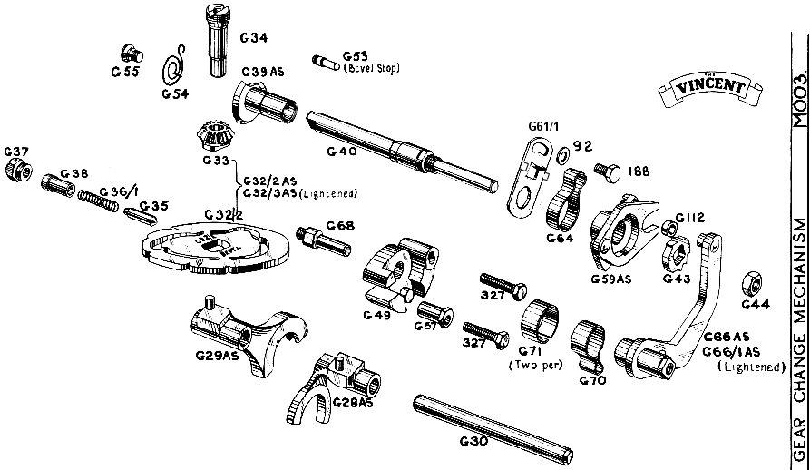 Adjusting
the Gearchange:
There are two things to fiddle with to make a proper adjustment of
a
twin
transmission, whether it be an original 4 speed, or an after
market 5
speed.
The two being the G57 and the G61. When the transmission is
in
neutral,
and the shift lever is in a relaxed position, and the G70 spring
is
supporting
the weight of the G66AS shifter arm, and the exterior foot shifter
arm,
the picture should be identical, i.e., the distance between the
outer
male
shifter pawl and the inner female shifter pawl, both for the
engaging
side
for low and the engaging side for second. One other 'must
do'
thing
is to insure G61 is pivoting on the shoulder of G40. It's
easy
for
G40 to slip away from it's shoulder on it's support bearing.
Adjusting
the Gearchange:
There are two things to fiddle with to make a proper adjustment of
a
twin
transmission, whether it be an original 4 speed, or an after
market 5
speed.
The two being the G57 and the G61. When the transmission is
in
neutral,
and the shift lever is in a relaxed position, and the G70 spring
is
supporting
the weight of the G66AS shifter arm, and the exterior foot shifter
arm,
the picture should be identical, i.e., the distance between the
outer
male
shifter pawl and the inner female shifter pawl, both for the
engaging
side
for low and the engaging side for second. One other 'must
do'
thing
is to insure G61 is pivoting on the shoulder of G40. It's
easy
for
G40 to slip away from it's shoulder on it's support bearing.
When engaging the male female shifter
pawls,
the
engagement of the pressure flats of the pawl should be
simultaneous
with
the contact of the relief's of G59AS and G43. The
adjustment of
G61
pretty well takes care of the pressure flat adjustment, and G57
pretty
much takes care of the relief of G59AS coming in contact with
G43
prematurely.
I've found that when you play with one adjustment, more than
likely
you'll
have to play with the other adjustment. When it's right,
you
should
be able to take the foot shift lever and visually observe the
point, or
apex, of G59AS, engage G43 in it's cleavage point,
simultaneously with
pressure contact point, and relief contact point. The most
common
mistake in adjusting the shifter, is that the relief contact
point is
premature.
It's fairly easy to adjust a transmission to shift well,
assuming that
when in neutral the G40 has very little backlash movement.
If
there
is excessive backlash, proper shifting cannot be obtained.
A well shifting transmission has a lot to
do
with
mass. Each shift requires a mass from a dead stop to
accelerate
over
a distance, and come to an abrupt stop. The mass in a
standard
Vincent
transmission, which is a four speed, that has to be started and
stopped,
is approximately 20% more than the after market five
speed. To
get
five speeds in a four speed gear box, obviously the gears will
be
thinner,
thereby lighter. There are two shifter forks in the four
speed,
and
three shifter forks in the five speed. The shifter forks
are much
lighter in the five speed than in the four speed, and much
stronger, as
they are made from steel. There is less movement in the
gear to
make
it shift in the five speed than in the four speed. The
large
engaging
dogs of the five speed, not only allow a better hold in angle
cam grind
(preventing jumping out of gear), it also is much better in
design,
which
enables the mesh of the gear dogs to actually relieve the cam of
the
shifter
fork from it's duties, and the force of the meshing dogs at this
point
actually turns the cam plate, not the shifter mechanism.
The five
speed is a much better design than the four speed in this
respect, as
it
allows slight roll off throttle shifts without clutch
disengagement.
The four speed transmission, when raced,
tries
desperately to reduce shifting mass by lightening the G32/2 cam
plate,
and the G66AS shifter arm. It's a good idea to
lighten the
G66AS when installing a five speed. Max Lambky
4/5/10
Adjusting the
Gearchange:
The
alloy block (G49) swings in an arc. If you loosen the two
bolts
(327)
and turn the eccentric hollow bolt (G57), you will find you are
able to
turn to high point and low point, the starting position would be
the
Middle
of this travel, then tighten bolts. Once you have placed gear
indicator
shaft in Second gear, you turn slightly the shaft to have
equal
gap
either side of that segment by altering the position of the small
plate
(G61), some have " Ears " some not, this was a modification or to
suit
those gear changes which were hard to adjust. The ears
restrict
travel
to not over or under shoot the gear engagement... at times one may
need
to bend the ears slightly. You must make allowances for any
Play
or Backlash .. or find another gear shaft with good segment,
etc.
Once you have done this and satisfied, you select the best
position in
gearbox by turning rear wheel slightly, so you can Swipe through
All
the
gears with gear indicator lever from bottom to top. It
may
take a bit of fine play to achieve. Place in Second gear
after
with
indicator. The reason for this is so you can with Gear
Change
Lever
select up or down in One clean movement. The full
travel of
lever must hit the Stop in alloy block Both directions. If
it
doesn't
and the gear falls in or fails to engage, then you alter
slightly
the position of alloy block to suit. This takes longer to
explain
than do. Mike White 5/1/09
Quaife 5 spd
Gearbox:
http://www.quaife.co.uk/shop_image.cfm/image/681/product/Vincent%205-speed%20Quaife%20gearkit
Glad you could read the Issue 3 G/A drawing
dated
27.03.03. More info below:
If it's of any interest, here are the ratios
of the Quaife / Surtees 5-speed
Vincent
box:
1st 1:2.46
2nd 1:1.61
3rd 1:1.34
4th 1:1.075
5th 1:1
...and the drive sequences (numbers refer
to
the
two end digits of the Quaife part numbers on the G/A drawing):
1st Selector 20
Leftward
28 -> 29 -> 13 -> 09 -> 18 -> 07
2nd Selector 20
rightward
28 -> 06 -> 14 -> 13 -> 09 -> 18 -> 07
3rd Selector 21
rightward
28 -> 06 -> 16 -> 18 -> 07
4th Selector 22
leftward
28 -> 06 -> 03 -> 13 -> 09 -> 18 -> 07
5th Selector 22
rightward
28 -> 06 -> 07
... and the small items' descriptions:
Item 2 (2 of): thrust washer (however, this
part
shown next to layshaft gear A-1E1-18 absent on my box, as that
gear is
a driven interference fit to layshaft spline tapers).
Item 172: needle roller bearing
Item 292: C-clip
Item 586: needle roller bearing
Item: 675: seal
A-1E1-04: thrust washer
A-1E1-05: plain bush
A-1E1-08: thrust washer
A-1E1-11: plain bush
A-1E1-12 (2 of): thrust washer
A-1E1-15: plain bush
A-1E1-17: plain bush
I guess A-1E1-18 wasn't manufactured as one
with
the layshaft as they couldn't have machined the dogs that
way.
Box main parts shown at
http://www.quaife.co.uk/shop_image.cfm/image/681/product/Vincent%205-speed%20Quaife%20gearkit
Phil Blakeny 6/9/08
Comet Trans:
Correct
one
is BAP. The B52/CP/GB boxes are all the wrong sizes
cases; shorter shafts and different gears/selectors from the pre and
post-war
Comets. One can make expensive mistakes buying these boxes in
the
belief they are BAP ones. Don't ask me how I know... Peter
Barker
4/15/08
Burman Drawings: http://vincenthrd.se/skisser.php
Various Grease/Oils for Burman Trans.:
* Castrol Spheerol L-EPO Semi-fluid
self-levelling
grease suitable for centralised lubrication systems and grease
filled
gearboxes.
* Penrite Semi-Fluid grease for Burman
boxes. It is best to do it on a warm day (or lace the
container
in
a bowl of hot water) otherwise it takes an eternity to
fill.
Do not try to run the bike for a few hours after filling as it
takes a
while for the grease to find its own level. Some people add about
50 ml
of light oil too.
* Millers of Brighouse sell a grease
Delta
EP000 in 3 Kg drums for a tenner. See their website
for
depots.
Very liquid.
Burman Gearbox
Oil:
It can be a cause of rapid bushing, etc. wear if the
grease
is too thick and does not flow
readily.
The
gears will tend to cut a track through it after which it does
not
flow into them continously. Also it will not enter tight
bushing
clearances. I suggest a small quantity of soft
grease
followed by sufficient 90 wt. gear oil to
acheve
the correct level. This way the soft grease gets carried
into
any leakage paths sealing them while the job of real
lubrication
is delt with by the gear oil . This works
nicely
in our Meteor and if not overfilled it
rarely
shows
any seepage. Sid 6/18/07
I have a Comet
with
a Commando gearbox. I fitted a
main
shaft seal from the Spares Company so that I could use automatic
transmission
fluid in the primary drive. I mounted the gearbox sufficiently to
the
left
so that there was room behind the clutch for a plate carrying an
oil
seal.
I was able to do this as I had mounted the gearbox in a fixed
location
and fitted a twin chain tensioner blade, suitably narrowed
in the
primary chaincase. All the springs were removed from the Vincent
ESA
and
the two halves welded together, the shock absorbtion being handled
by
the
rubber inserts within the standard Norton clutch. This results in
a
rigid
assembly and a very sweet transmission. There is absolutely no
justification
for fitting a triplex chain to a Comet, there's isn't enough
torque
there
to require it. Roy Cross
It is possible to get the gearbox
out of the Comet without
dismantling
the
whole machine though obviously the clutch will have to be removed.
It
all
depends on the two chain adjuster bolts that allow the gearbox to
swivel
backwards and forwards for primary chain adjustment. Ideally all
you
need
to do is to unscrew these two bolts and remove the gearbox
mounting
bolts
and with a lot of cursing and 'ackling' (wriggleing about) it will
come
out. Warning ! Unfortunately it is usually impossible to remove
the
chain
adjuster bolts as in service the working ends that bear on the
lower
gearbox
mounting bolt bell out. Any attempt to remove them will strip the
threads
in the gearbox casing. However I have managed to remove and
replace
several
Comet gearboxes over the years with bolts that were belled out. It
is a
tedious process requiring much patience. What is needed is to keep
adjusting
the positions of the adjuster bolts relative to each other and by
trial
and error, so far, I have always found a position where I can
wiggle
the
gearbox out. Tightening of the Gearbox is usually the drive side
layshaft
bearing. Heavy
grease never gets to it hence the advice to
put
in the odd spoonfull of engine oil. Hugo 3/10/07
Pre-war, the Burman
BA-
BAP
traansmission was made with
three
sets of gears:
* HS, which is the set we know on the post-war
Comets.
* LS, which appears to be Trials: only the
constant
mesh (4th.) gears differ from the HS.
* TT gears as fitted to competition models.
Post war, only the HS ratios seem to have
been
manufactured, and as we know, the Flash used the Albion box, for
which
a wide selection of gears were available. I do not
consider
either
the HS or TT gears were really the correct ratios for their
respective
uses. It would, of course, be possible to redesign each set,
which
would
probably mean replacing virtually every gear in the box.
However,
for road use, there is an interesting compromise based uniquely
on
pinions
which once existed: to use the standard 1st. and 2nd. pairs
which
presumably
exist in your present box, in reasonable condition, with the TT
4th.
and
3rd. pairs of gear- that is, changing 4 pinions. This
would give
ratios of 1:1, 1.16, 1.45 and 2.3, or 100, 86, 68 and 43%.
Bruce McNair 2/9/02
Pre-war Burman
Transmission
spares list:
http://www.btinternet.com/~paul.wirdnam/sq4/1930/burman_frameset.htm
Synthetic oil
is
banned
from being used with our kind of bearings, simply because the
coefficient
of friction is too low for the rollers and balls to rotate, causing
them
to skid, and wear with flats on them. Any one out there have any
Long
term
usage with Synthetic, e.g. Mobil 1 ? And had a look at the results.
Trevor
A quick check for gear
changing
problems is to change gears with one hand - with the
bike on
the rear stand - whilst restraining the indicator lever G81's travel
by
holding the indicator with the other hand. When the gear lever
has
reached the end of its travel carefully check to see if there is
anymore
movement of the indicator lever to fully engage the gear being
selected
by moving the indicator lever in the same direction it was
travelling.
If there is any more movement of the indicator lever required then
the
camplate G32 is not travelling far enough by gear lever operation.
If this symptom can not be cured by adjusting the selector
mechanism
then the cast alloy block G49 needs opening out with a file to
allow
more
travel. Check that this is infact the problem by carefully
adjusting
G57
stoplate adjuster so that more movement of G81 is required to
engage
both
3rd and 4th gear.
This will prove the need for the block to be opened out - a
fairly
simple
job with a file and G49 in a bench vice 'a little at a time' till
you
have
the right amount of travel - being careful to remove the metal off
the
place on G49 that stops the travel of the gear lever or maybe a
little
off both stops with G57 in the centre of its travel ( to make
allowance
for future adjustment). G49 has a concave shape where the metal
has to
be removed - there is no need for this shape, a flat surface is
all
that
is required to limit the travel of the gear lever.
I have had to carry out this job on at least 3 separate bikes
after
which the gear change has been transformed - having giving the
gear
lever
just that little extra travel.
I have also discovered the importance of adjusting the battery
carrier
nuts E80 to compensate the load on the pivot bearing plate G50
when the
foot rest hanger bolt is nice and tight for a really nice gear
change.
If there is any stiffness in the gear change when the engine is
hot -
try
slackening off the hanger bolt just to see if this is the
adjustment
needed.
If so, adjust the 2 E80 nuts outwards and pinch up the foot rest
hanger
bolt again and carry on riding. Andrew
Rackstraw
8/14/00
When you get a situation where the box jumps
out
of top gear as your try to grab a handful , the usual
reason
is that the detent did not go into its position on the camplate,
this
is
the positive position. On some later machines you can find
that
the
detent Cannot even get that far. The G39 being stopped from rotating
into
position by the bevel stop pin. This can only be checked on assy.
with
the gearbox assembled and with the detent out, look into hole to see
where
the camplate is. If you have had a problem with top gear
jumping,
this is the cause. Trevor 8/14/00
Denny Delzer asks why his gearbox jumps out of second gear ? This
means
that the detent is not sitting
in
the
camplate perfectly, this could be for two reasons.
1 On changing gear the gear pedal is depressed too lightly ,
allowing
the gear to change but the detent does not sit in position.
2 The set up of the gearbox does not allow the detent to sit in
position.
Even if you have as you say NOS parts or good condition parts in
the
box, this is not a reason to say there is nothing wrong.
So what you have to do to check out the set up, is to remove the
detent
and visually check if the camplate is in position, when the box is
in
second
gear. If it appears to be, replace the detent spring, and
test
ride.
If the problem still occurs you have a problem with the set up.
The
only
way to check then, is to use my checking fixture and sort
out the
problem. I won`t begin to tell you what could be wrong. I`ve
lost
count. Trevor 6/16/00
Improvements to
shift
quality
Many - even most of the Vincent
motors we have dealt with in our work lack one small but extremely
valuable
Works up-grade dating back to the very early years. A simple
looking
alteration first suggested by one of the fine road-testers active
then,
one Bob Brown. Very keen and dissatisfied with the tendency to
over-shift
present in too many units that he rode -Bob came up with the notion
of
adding restraining tabs or ears to both sides of the pawl carrier
centralizer
plate G 61. This became G 61 /1 with the addition of two projecting
motion
stops brazed one to each fore and aft edge. So utterly simple
it
seems, yet properly positioned truly worth more than its weight in
Gold.
Perhaps because it is not so drawn in our B/C Parts
Books
yet
carries the corrected part number. Few have picked
up
on it and the magic it performs. My first exposure and
explanation
came to me way back in 1953 while shoping at the Works Spares
counter
where
the modified piece was handed me and called the Bob Brown
Special.
Friendly chap behind the counter there confided that I'd surely want
one
of these as he dropped it into me waiting hand.
There is a subtle touch to getting it swung just so in
order
to
derive the best results out of those metal stops that Ill
try to
convey to you my friends. The aim is to snub off excess
inertia /
momentum imparted to the spinning cam plate during a too
spirited
shift . This energy tends to rotate the plate past its next
notched
position -- forcing excess rotation to drive the plate - lifting
the
indexing
plunger up out of that desired notch and so allowing further
rotation
towards
- or into the following ratio selection. Over selection
results
. My experiance when fettling these pieces is to allow the ratchet
to
closely
approach - not enter fully - the up coming notch. Notice my
word
choice carefully . Closely approach only and Not fully enter the
cam
plate
notch. Thus the tab contacts and acts to slow/snub off
the
excess speed, to where the spring driven detent plunger can
take
over control and deliver sweetly to the bottom of the notch,
that
unwanted momentum already absorbed in the slight flexing of
the
arresting
stop. Only the spring pressure remains to fully seat the plunger
into
it's
homing notch. Barely any of the shift lever thrust and
rotational
energy exists in the plate as it enters the edge of the notch
slope.
Duplicated in both directions and I've seen very
little
need to bend the stops much, and the shift becomes dead reliable
and
pleasing
beyond words. Much of the ease and sweetness is dependant on full
clutch
release, and I shall delve into that clouded subject
in my
next effort , however let me say that after all these
decades
I am still and ready to prove that the original Vincent
clutch
can
deliver better feel and function than a
multiplate
conversion
for greater mileage and less parts wear than any in my
experiance.
S.M. Biberman 21 Mar 2000
return to thevincent.com