
Scroll down for Max Lambky's Restoration
Tips... an entire series of Great Tech Articles. 2/24/10
I stupidly lost the first digit of my right forefinger just this way. My '49 Matchless Twin gobbled it up just like that ! Never do this chore with the motor idling over in low gear, the beast Will grab the brush And your fingers in one moment of terror and pain that lasts a lifetime. You have been warned, its only to be done with a dead motor while Very slowly rotating the wheel with the other hand. Note, there is a second bit of this material containing useful tips you should read. Only a recognized Brand of motorcycle chain is suitable . Ignore bargan offers . Sid Biberman 2/24/10
But silver solder does come in a lower temperature heat range for gas type torches without oxygen and iron use. I prefer this product MG120, also known as MG120A. This product‘s working temperature is 430 degrees, perfect for soldering iron use. The MG product has 3x the tensile strength as these electrical types. These MG products use a flux core and cleaning agent for the preparation of bonding. The MG120A has a syringe applicator for the cleaning agent whereas the MG120 is a bottle. It is available at welding supply stores.
The key to a strong union is wetting and capillary attraction. Wetting is the ability of the molten solder to coat the strands surface. Capillary attraction is its ability to flow or wick. I prefer to ‘’tin’’ the inner cable end after I have slid my end fitting on to the inner cable first. This allows you to ‘’work over’’ /mushroom or flair the multiple ends more easily to prevent the dreaded pull-out. Pull the inner cable back to the fitting and solder. Trim or file the fittings when done.
Remember to lubricate all your non Teflon lined cables once a year by buying one of those simple spray type lubricators available at any good local m/c shop. I use a spray can of white lithium grease. These devices clamp over the outer cable end, have a small rubber hole built in and the grease squirts inside, down the cable housing through to the end. If you use a junction box with a single throttle cable to twin cables make sure you protect that junction from dirt and debris, clean and lube with light grease once a season along with all of your other cables.
Messer Company - MG Welding
Products
N94W 1455 Garwin Mace Drive
Menomonee Falls, WI.
53051 USA
(262) 255-5520 --
(262) 555-5542 fax#
Hardness 15 10 kg/
mm2 approx 15,000 psi
Melting point 430 degrees F 221
degrees C
Available in :: 1/16’’, 3/32’’,
1/8’’ >>>> use 1/16’’ for cables
Jim Wilson 1/24/10
The very first thing this reporter
has to do is give a hearty “Thank You” to all the Vincent folks
who have contributed to this article. Your comments and
knowledge are central to its existence.
If you are new to the world of Vincent
motorcycles and actually plan to ride your machine there are
several reasonable modifications you will want to consider to
make it a more tractable vehicle.
One of the first things you should
have is a basic library. You should consider buying;
Spare Parts List; Rider’s Manual; Know Thy
Beast by E.M.G. Stevens; Vincent by Paul Richardson; Forty Years
On & Ten More Years (two separate books) by Jeff and Lyn
Bowen plus a copy of Original Vincent by Jacqueline Bickerstaff
if you can find one. Both Bowen books are available from
VinParts and VOC Spares Co. has Ten More Years. Jacqueline’s
book is now a collector’s item and needs to be reprinted.
If for example, you need to adjust
your gear change mechanism the advice you seek will probably
point you toward “Richardson” page 76. Stevens’ work is not only
a thorough treatise that dissects the machine, it will provide
you with a reference to locate every screw thread and a
materials list.
The possibility exists you may want to
become knowledgeable about virtually every segment of your
machine, the problems and modifications that have been enacted
before you. You will find no better reference source than the
two books listed by the Bowens. They are a compilation of MPH
articles over the past half- century that will give you an
education unequalled in any other books on the subject. While
there is no substitute for hands on experience you’ll find those
who have gone before you have written about your machine and
have been where you are going. For example, you may not know how
to set your timing to re-install your magneto. You’ll find a
step-by-step article on how to locate top dead center, the first
procedure necessary to accomplish your goal.
One of my goals is this article is to
provide, most especially the person new to the world of
Vincents, an overview of the machine and mods that can be easily
accomplished. Let’s start at the front of the machine with our
braking system.
BRAKES
The twin drum brakes on the Vincent
were considered to be the best available when the Series “B”
twin was introduced in 1946. The Motor Cycle magazine did a road
test in May of 1947 and reported a stopping distance at 30 mph
of 26’ on dry pavement. The Series “A” machine stopped in 27’
reported an Aril 1938 edition of the same magazine. Your
reporter had measurements of 22’, 22.5’, 26’, and 33’ in four
attempts on my own Series “C” and flat-spotted a rear tire
during the tests. From 50 MPH I stopped at 64.5’, 60’ and 75’.
The Vincent brakes have been the
subject of countless articles on how to make them more efficient
but at the end of the day, replacement appears to be the only
method of achieving modern day measurements. In this reporter’s
estimation, riding a stock drum-braked machine in a world of
disc-brake automobiles is a dangerous proposition made even
worse if you ride two-up.
Several members have installed disc
brakes and it is outside the scope of this article to detail the
necessary modifications. One Dave Lambert made a professionally
produced kit to accomplish the task. This reporter rode Matt
Biberman’s Shadow equipped with the Lambert discs and it worked
to expectations. It was perfect. Late news tells us Dave has not
sold a kit in over a year and is not actively seeking business.
Nevertheless he may be contacted at: 132 Beaufort St.,
Derby DE21 66BB U.K. Phone: 44 332 369-047 The
chance exists he can direct you toward disc installation as he
has solved the problems in a craftsman like manner.
Within the past three years we have
seen two additional sets of brakes on the market for our bikes.
The first set is a twin leading shoe conversion advertised
frequently in the MPH. It is made by Vincent Speet and in a note
from rider Peter Volkers he tells me he was able to stop in
16.8’ from 30 MPH and 37.5’ from 50 MPH utilzing this set-up. As
noted, Peter is a journeyman rider who has an earned reputation
of being extremely proficient and fast. This reporter knows from
experience to pull a very good front brake on full chat takes
perfect conditions, and a good dose of bravado. Peter used only
the front brake in his test.
The point is, the twin leading shoe brakes
will stop your Vincent rapidly if you have the ability to use
them. Former MPH editor Robert Watson was demonstrating the
efficiency of his twin leading shoe brakes and literally locked
up the front wheel at 60 MPH with two-finger pressure. Robert is
another accomplished fast rider who wants the insurance of
knowing he can, if necessary, lock the front wheel. The new
brakes are not as efficient as discs, but from all reports they
seem to be the next best thing.
This system uses a dual pull cable
system, supplied. You won’t utilize the balance beam (F55) as it
is no longer necessary. Vincent Speet also reports he will have
old style levers available soon as well.
Information on the twin leading shoe
brakes is available at vspeet@vsmmetaal.nl. Vincent makes
regular and Lightning style plates for his units and they are
priced at 890.00 and 1150.00 Euros respectively.
Our own VOC Spares Company has
obtained the exclusive distributorship on the latest braking
system for our bikes. New drums and backing plates which are 8”
in diameter are now available. A fine color photo of the new set
designed by Hugh McAllister is shown in MPH 716. These brakes
deliver a hundred percent increase in friction (braking) area.
To date, I have not read of a report of their actual performance
and stopping distance. Like the twin leading shoe brakes, they
require no modification to the bike for installation other than
making some new cables.
We understand one Eric Kruse of the
German section has made some Shadow drums in aluminum with the
liner shrunk in. He has used Ford Fiesta brake drums for the
liners but we’re sorry to report I have no additional
information on his work. E mail for the German section is
germany499@voc.uk.com
I won’t address our rear brakes
because by far and away, the bulk of your stopping power on a
vehicle in forward motion is on the front. Of course discs can
be fitted to the rear as well and Dave Lambert also made a kit
to do so.
For those of you who are using the
Lightning style backing plates Russell Hartley makes some
beautiful air scoops with etched gauze. Ordering info is below:
Yes they fit straight onto Lightning back
plate I have sold some to owners who have fitted my scoops
straight onto the club’s racing alloy plates.I usually sell 1
scoop I gauze and 3 2BA cheeshead screws For
£23.50 (You will need 3/16 whit screws for alloy plate I
use 2BA or 5mm for the steel plate as I have sold some sets to
fit on other bikes ) Alloy air scoop £15.00; S/S gauze
£7.50; contact russellhartley314@btinternet.com
Phone 01767 650049 UK telephone
Jeff Bowen, for one, has successfully
fitted a set of Grimecas to his bike and other twin leading shoe
set ups can also be made to work, but none are a direct bolt on
operation. For those interested in the Grimecas see
www.ajs-shop.co.uk
SHOCK ABSORBERS & SPRINGS
Moving upward on the machine we can
address our shock absorbers. While high mileages have been
obtained with the stock shock absorbers, it must be noted our
originals were among the first “airplane” style hydraulic shock
fitted to a motorcycle. I believe the first bike fitted was a
Velocette and if memory serves correctly our engineer Phil
Irving created that shock. You should remember hydraulic shock
absorbers were new to the automotive world in 1946 and the first
ones had their share of teething problems.
You’ll find numerous articles on how
to refill your stock shocks as well as cures to prevent them
from leaking in 40 Years On. Personally, I recommend replacement
of both front and rear and I believe doing so along with
attention to our springs and rear suspension method, especially
on the Series B & C machines, can transform them into great
handling modern day vehicles. This is not to say the stock shock
absorbers will not perform adequately when in perfect condition
but it is difficult to argue with more modern technology that is
now available to us.
For years one of the most popular
shocks to fit to the Vincent has been the Koni and I believe it
is now called an IKON. While positive comments may abound rider
Mike Alexsander noted,”mine didn’t fit without grinding the
front mount and on the rear I found they bottomed out on the
smallest of bumps. They were returned and money was refunded.”
Contact info is:
Recommended Service
1064 Revere Ave
San Francisco CA 94124 USA
P: 415 738 9441 (Dave - Call ofter 1pm
West Coast time)
E: ikonusa@gmail.com
W: http://www.ikonsuspensionusa.com
The Armstrong brand has also been
proven to be reliable. There is another shock named AVO as well
that has gained popularity. The last I heard from supplier
Russell Kemp had him installing one of the AVO units on his own
machine so this reporter is taking for granted the brand is
well-respected as the engineering oriented Jeff Bowen was the
first to install the AVO’s on his machine and penned an article
for the minor mods necessary to fit. Part # for the AVO is PA
100/75. See MPH 657, Oct. 2003 for a report. Contact info:
www.Avouk.com
A note from Chris Chant says: My 'C' Rapide
came to me in the late 80's with Armstrong units fitted. 30k
miles later they still perform nicely along with series D front
(softer) springs.
My recollection is that Koni's were good on
the rear but rather too stiff on the front for solos.
A note from Steven Lindbloom states: I
personally do not think stock shocks can be made to work well
and always have wondered what the high priced rebuilds available
now actually do besides a better seal. I did a lot of
experimenting with them at one time, including grafting valve
bits from various later Girling shocks on, but they never seemed
to work all that well.
The inspiration for the Thronton system
seems to have been a comment by PI in one of his books, that
with good damping it is possible to greatly reduce spring rates,
and greatly improve ride and handling. He probably realized this
too late for Vincents to take advantage of it, and later
improved shocks like the Konis were always limited by the stock,
heavy-rate springs. It was not until the Thornton that someone
got around to matching softer longer springs and very good
dampers, with impressive results. Thortons shocks are made by WP
(Works Performance), but I believe the specs for that particular
model are proprietary to Thornton and can only be had from them,
but there are other Vincent people who have worked out their own
specifications with WP. Similar softer, longer springs are
occasionally available from other sources much cheaper, but
unless they are used in conjunction with really good dampers may
disappoint..
Konis were just shocks, no spring, same size
as stock ,not terribly sophisticated, just a fairly crude
adaptation of a standard design to fit the Vincent, rather than
something really engineered for the machine. But late 50's
rather than 40's technology so still quite an improvement over
stock. Lack of machine-specific engineering is actually, in my
opinion, the problem with just about all the Vincent shocks,
with a possible exception of the WP since their modular method
of handling valving etc. offers a lot of flexibility for
customizing, given a discerning customer to handle the road part
of the development.
Spax, who has always had a good if somewhat
cultish repute for their auto shocks was induced to make shocks
for the Vin once, but abruptly pulled out after they were sued
by a customer, feeling the potential market just wasn't large
enough to justify the risk lawsuits. They had a recall, but many
owners chose to keep them. They were externally adjustable, but
other than that fairly comparable to the Konis.”
Personal experience has taught me the
shock absorbers supplied by Laney Thornton are superb at both
front and rear. Because I was involved in the auto racing
industry for three decades I had access to a shock dyno and
tested mine after 25,000 miles. They were in perfect condition,
and I have covered an additional 40,000 miles thus far with
them. Again, the technology for great shocks just wasn’t
available at the time the factory produced our machines.
The Thorntons are distributed by Dave Molloy who can be
contacted at molloy@inrech.com. Thornton is a regular MPH
advertiser.
Here’s a note from Dave Molloy from my
research:
Carl, thanks for you inquiry. The
basic features of the Thornton suspension system are two fold:
1) the springs are about 20% softer rate than standard but are
longer to give more preload to maintain the ride height and 2)
the shocks or dampers are a modern design manufactured
exclusively for us by Works Performance and are valved
differently front to rear to match the differing spring rates.
We do make front springs and I make the 1" longer inner spring
boxes to help align the inners and outers at full extension
which is 1" longer than standard Vincent springs. As of this
date the standard front and rear kit is $840 and the longer
spring boxes are $120 a pair extra. Dampers alone are $290 each.
Our German friends have written to me
and stated:
“Our program includes gas shock
absorbers made in the original style as well as improved
cylinder heads, a combined dynamo/-ignition system etc.
The website to check is
www.vincentsparesgermany.com
Information supplied by:
Michael M. Burkert
Ernst G. Ahrens GmbH
Wendenstrasse 29 - 20097 Hamburg Germany
Telephone ++49-40-232384 -
Facsimile ++49-40-232387
Homepage: http://www.egah.de -
E-Mail: michael.burkert@egah.de
Your reporter has not seen the gas
shocks (or other products) noted in the above e mail but we have
no doubt the craftsmanship is first-class. I am surprised and
saddened the German products have not been advertised, or
publicized in our MPH pages. First, we know our editors will
gladly publicize new products for our bikes, and secondly it
seems only reasonable anyone making a Vincent part would surely
want to inform riders world-wide and the MPH is the natural
publication to do so.
Rider David Dunfey has seriously
addressed the spring questions by actually having some new front
springs made. His are 14”in length and had two rates made:
75lbs/in and 110lbs/in. Comparatively the Thorntons are around
50-60 lbs/in spring rate. David’s theory is that the stock
springs must be compressed at least 3” which means they have a
tendency to extend the front end. The shorter springs want to
“settle” down from full estension. The 75 lb springs were
designed for the Comet and the 110 lb for the twin. In practice
David’s springs have proven successful, plus they can be
installed without the use of a compression tool.
David didn’t make the springs as a
business venture but some are available through Sam Manganaro's
E-mail at hrd998@verizon .net. David is hoping the club or
Thornton will be impressed enough to make them available.
Colin Jenner of Conway Motors, Ltd.
has provided me with an impressive list of mods he makes for the
Vincent which includes the longer Pettieford springs popular for
decades as well as alloy racing type brake plates and he notes
he makes, “modified and improved Vincent dampers.” He also
supplies heavier front brake cables with longer adjustors. The
Pettieford springs are the same wire diameter as stock, just
longer.
Veteran Vincenteer Justin Mackay Smith
(our current advertising manager) had some longer springs (and
rear spring boxes) made that work perfectly on the reporter’s
bike. Justin was not interested in going into the spring
business but it is entirely possible to clone what he made as I
had springs wound to my specs in England once. He can give you
the specs.
Concours judging aside, we have often
heard the very reasonable argument stating basically if a
particular technological improvement had been available at the
time, the originators of our machines would have included
it. By the mid-Fifties when the last Series C and the D
were produced, there had been improvements in shock absorbers
and the disc brake was at least being introduced on some racing
vehicles. Thus to this reporter it is not heresy to make said
modifications. Equally as important to this rider was the change
in the method of supporting the rear of the seat. Our B’s &
C’s had the seat hooked directly to the rear swing arm assembly
which caused the back of the seat to rise and fall half the
distance the rear wheel traveled up and down. The factory fully
sprung the rear wheel on the Series D by running struts downward
which ultimately connected to the engine. Countless owners of
the prior series machines have copied the arrangement and have
seen marked improvement in ride and handling. Personally, I
wouldn’t want to ride a machine with the stock struts after
experiencing the handling after deleting them. It is a simple
mod to make struts and connect them to the FT 108 Footrest
Plates. On my own machine I spent countless hours fabricating a
goofy looking battery carrier that ultimately cantilevers its
way over the rear mudguard, holds two passengers and the largest
panniers I have ever seen on a Vincent.
Speaking of panniers there is a great
looking photograph of what are called stock Vincent panniers on
page 219 of Know Thy Beast. While painfully small their design
and construction is superb. Member Derek Sayer super sized the
design and has produced a few sets that are equally as gorgeous,
but we haven’t seen them advertised in the past several years.
It is of course still possible to fit the once very popular
Craven bags. However, even author E.M.G. Stevens said of the
Craven mounting system they are, “positioned too far back and
too high, whilst the system lacks the necessary rigidity.”
Consequently you are pretty much on
your own when it comes to fitting a set of panniers to your
machine. This reporter believes you will find the possibilities
much greater if you do in fact unhook the rear of the seat from
the swing arm assembly and consider building brackets that can
be mounted to the seat itself. You will undoubtedly achieve a
better handling vehicle by allowing the rear wheel to be fully
sprung.
As we are riding what the designers
called “a high-speed long-distance touring machine” it seems to
this reporter to be a sad state no one has come up with an
improvement for fitting a large set of panniers to our bikes.
STEERING HEAD BEARINGS-TANK SLAPPERS
The original ¼” steel balls, 20
of them are required for each bearing and upon occasion the
bottom cup has been found to be loose. Christian Patzke has
created a tapered roller conversion kit for all Vincent H.R.D.
head races and reports he has sold over 100 of the units that
are definitely a good idea to install. A minor amount of
material must be removed at the bottom of the bearing housing to
allow the cage to clear. This can be machined, or even ground
with a rotary hand tool. His e mail is
info@patzke-fahrzeugbau.de and his website is
www.patzke-fahrzeugbau.de
The Vincent, along with a multitude of
other motorcycles can experience a phenomena known to
motorcyclists as a “tank slapper” whereby the front wheel will
shake violently from side to side. I believe the engineering
term for this condition is dynamic coupling. You will feel as
though the machine is a piece of spaghetti attempting to throw
you off into oblivion. Many of us have experienced this
uncontrollable condition and the very first question asked is,
“Did you have the steering damper tight?” Well, not tight, but
just biting. You don’t want to ride your Vincent with a loose
steering damper. In fact, many have installed an exterior
steering damper in the form of a gas-filled shock that
ultimately attaches to the front cylinder head. You’ll find a
how-to-do it in Forty Years On. These wave like forces pass
through the machine vertically, horizontally and laterally and
are deadly. You want your front end in perfect condition.
ELECTRICAL SYSTEM
Alternators & Ignition
Electrical System: The reader should
bear in mind this reporter is not an electronically oriented
individual but one who has simply paid attention to the
victories and vagaries of the Vincent electrical system,
especially after experiencing significant problems with the
standard system.
We know the standard voltage
regulators of yesteryear have been much improved upon by the
advent of the solid state regulator. I can report from
experience my old Miller generator performed brilliantly for
about a decade after having it rewound along with the
utilization of a Ken Bell regulator. Sadly, Ken has passed away
and after many years of usage so did the regulator I installed
on my bike. It ran a 60 watt quartz halogen headlight bulb and
my heated hand grips admirably. I did not find a replacement
that worked as well, so I ultimately opted for a unit known as a
McDouglator.
The McDouglator was conceived by John
McDougal when a friend brought him a Kubota tractor alternator.
John devised a gear case to drive the unit that utilizes a set
of gears that literally clone our cam drive gears. I believe he
has sold well over one hundred units that have performed
perfectly. I know mine has and have heard nothing but great
reports on the installation. John doesn’t advertise and the only
way I know of contacting him is via phone at 604 327-1019 or
write to him at 82 E. 50th Ave., Vancouver, BC V5X 1A2.
There is a detailed article about the unit on www.thevincent.com
Of course the alternator is 12 volts and since it was designed
for industrial usage it is trustworthy on our bikes and is a
direct bolt-on unit with no modifications. John uses the Kubota
regulator and he has attempted to destruct it in all manner of
operations and it has passed the most rigid tests. The regulator
is large and won’t come close to fitting in the old stock case,
so I mounted mine under the battery carrier and put the stock
one, empty in its usual position so the passer-by glances and
doesn’t notice the whole plot has been modified.
One of the most popular generating
units on the market today for our bikes has been developed by
Paul Hamon and is called the Alton. Paul has had, I believe
three incantations of his charging system and the latest has
received magnificent praise from users world-wide. Paul also
supplies a modern rectifying regulator (negative earth) and
promises a two year replacement warranty. I can report from
experience Paul is a gentleman of the first order to do business
with and we in the motorcycle world are fortunate to have a man
of his dedication and craftsmanship interested in our hobby.
Contact at: formats@blue-mail.com Phone: (Int’l) +33 298 283575
There is yet another reliable system
available developed by Norman Walker and Dick Sherwin that uses
a Citroen 2CV alternator which will provide 12 volts and 30
amps. We have not seen the kit advertised but have heard many
testimonials as to its efficiency. The alternator is belt driven
and of course bears no resemblance to the stock set-up. Contact
information is:
Dick Sherwin [dicksherwin@btinternet.com]
and NormanWalker [enw07@btinternet.com]
There are numerous voltage regulators
on the market which will provide good service but it is outside
the scope of this article for me to compare them all. I refer
the readership to the popular website www.thevincent.com and
search under “Electrics” to gain some knowledge. Overall, most
of our Vincent suppliers can make regulator recommendations and
many are supplying units that fit into the stock Miller cases.
It has been reported some units actually leak amperage and may
cause you a dead battery within a fortnight, so research is
suggested.
Hartmut Weidlich, versatile machinist
and Vincent rider who hails from Germany notes: “If an Alton is
used any regulator from a Jap bike that has permanent magnets in
the flywheel such as RD 250/350 or SR/XT 500 will work.”
Doug Wood the man who invented the
jtan e mail service dedicated to the Vincent is also a magneto
and dynamo restoration man. He notes some of his customers still
insist upon restoration of their old electro-mechanical
regulators as opposed to replacing them with the modern units.
.LIGHTS & BULBS
Given our modern technology there are
more options for lighting your vehicle than ever before. Member
Paul Goff at: www.norbsa02.freeuk.com (and a frequent MPH
advertiser) offers us an alternative to fitting a modern
reflector in the standard headlight shell by supplying a line of
quartz halogen bulbs with the original Bayonet cap and British
pre-focus bases. They snap into the existing headlight and
provide much better lights. They are available in both 6 and 12
volt versions. Paul also supplies LED conversions for the stock
tail-lights that are brighter. He supplies daytime pilot bulbs
as well.
There are several reflectors you can
fit into either the 6 ½” or 7” headlight shells that will
accept quartz halogen bulbs. Member Jim Wilson has researched
many units and gives me the following:
The Hela 7003 and the Puma 440-498
0638 will work in the “T” clip variety while the 7” split rim
will accept the Hella # 1A6 003 402 812 12 volt unit 154 or #
70003 fits the 6 1/2:” “T” clip while the # 70476 fits the 6
½” “T” clip. The only contact we have for Puma is in the
US at info @puma-access.com
Your reporter found that a Honda V-45
unit from a 1982-83 bike snaps into the original clips with no
modification. However the outer glass on this unit is caulked in
place and must be broken out first. I have run mine for about 15
years. I am told a Suzuki GS500E from the mid 1990’s will also
fit and also a Honda Super Dream unit # CB2 50N for UK
applications that dips to the right.
Steven Lindbloom reminds me that you
can use any 7” light unit you like in the 6 ½” shell if
you utilize the Dietz reproduction rims.
Jim Wilson also reminded me that
Chicago Section member Paul Holdsworth and Glen Shriver made a
deal with Radiantz to make 50 LED conversions for the tail-light
assembly a few years back that had 46 dual filament 12
volt bulbs and three white bulbs for the license plate.The
section sold all the units but Radiantz may still supply the
internals. Contact info at:
Phone: 877-469-4241; Mail to: 96106 Ferrelo
Rd. Brookings, OR 97415 USA
BATTERIES
We include the following only because this
unit has such a high amp hour rating and will fit inside an
Exide case. Information provided by Mike Hebb:
“It fits very nicely and puts out 14 Amp
hours which is unusually hi for a small 6 V. Size is 2 3/4
x 4 3/16 x 5 1/2. Called the dealers and the price was $29.00,
two years ago. http://www.parmakusa.com/Additional/parts.htm
Your reporter is utilizing a Yuasa
YTX7A-BS 12 volt battery that is just a tad tall for the Exide
case and is rated at 6 amp hours. The gel cell batteries have
also gained popularity.
Knowledgeable Trevor Southwell
suggests a Hawker Genesis or Odyssey unit.
A hollow black battery case and shell
top, part # 99-920, cost $54.56 is available from
www.waldridge.com as well as from many Vincent suppliers.
IGNITION SYSTEMS
Your original magneto, restored with a
modern day condenser will provide you with years of service.
Nevetheless, I recall having veteran Vincent owner Dick Perry
comment to me, “If you really want it to start very easily, and
always idle, you’ll go to a battery ignition.” Your
reporter used a magneto for about 15 years and it was adequate
for the job, once I learned precisely how to start the machine.
Today we have more choices than ever
before.
First, the Series “D” distributor can
provide excellent service especially if you have the unit
rebuilt. Roy Price performs the function and provides a new
distributor for 165 British Pounds. He also rebuilds the ATD for
105 Pounds and supplies new stronger units for 149 Pounds.
Contact information is: Roy Price, 14 Heron Court, St. Neots,
Cambs PE19 1TH Phone: 01480 473 225. He is a regular MPH
advertiser.
John McDougal has a Harley-Davidson
based battery operated conversion available as well. Address
printed previously.
The creative Francois Grosset has what
is reported by no less an authority than Patrick Godet to be a
fabulous electronic ignition system coupled with proper
integrated mechanical advance available for 500 Euros. The
Grosset ignition is fitted as standard equipment on Patrick
Godet’s Eglis, and Patrick told us he considers it to be
the finest available on the market. Patrick Godet has had
experience with virtually every ignition system on the market.
Francois and his son have also
developed a small CNC machine and they are churning out
specialized items from motorcycle parts to artwork. We had a
glimpse of some Perspex they engraved with the Vincent logo,
another of a pair of valves and a humorous piece sure to be
loved by those who are not fans of Japanese bikes. Francois is
one of the industry’s more creative and artistic men whose
presence is appreciated.
Contact information is: Francois
Grosset, Le Pont Ricoul, 35720 St. Pierre de Plesguen, France. E
mail: pontricoul@aol.com
Tony Harris is the man who has revived
the old B-TH name with his self generating electronic magneto
also with electronic advance/retard. The B-TH unit has also
received rave reviews and your reporter is a very satisfied
customer. My own bike starts easier and I now trust the idle
more than ever. Tony’s twin unit sells for 510 British Pounds
while the Comet unit is 460. Contact information is:
website:http://www.bt-h.biz and e mail is bt-h@bt-h.biz The
devices are regularly seen in MPH ads.
Your reporter does not have enough
technical knowledge of other units on the market such as the
Pazon and Boyer Bransden to give you an educated report, but
both have been utilized successfully on our bikes. The Pazon
unit has recently received great reviews on the club’s forum and
they are concentrating on the Vincent unit so it is surely one
to be considered. Their web site tells us the system was
developed with assistance from veterans in the industry, Kirby
Rowbotham and Bob Dunn.
Contact info: http://www.pazon.com/
and VinParts is a dealer for the Pazon systems.
John Healy, the man who quietly
supplies Vincent parts in the US through his Coventry Spares
company spent a good deal of time one day explaining to the
writer just how to install my ATD back in the days when we
didn’t have the choices now available. It is wonderful to see
several units on the market.
Last and certainly not least is the
advent of a combination dynamo/magneto unit made in Germany and
publicized on the aforementioned German spares website. We have
been unable to obtain further information on this unit.
ELECTRIC STARTERS
The aforementioned Francois Grosset
solved the electric start problem for Vincent twins with his kit
that leaves the stock kick starter in place, and usable.
Francois’ craftsmanship and dedication to the Vincent are well
known in the Vincent fraternity and his “electric leg” has
turned many a Garage Queen into a daily rider. Pricing starts at
1500 Euros, contact information already provided. He regularly
advertises in the MPH.
Master Vincent engineer Bob Dunn has
also installed electric starters on Vincents but to our
knowledge does not provide a kit. Bob is well known in Vincent
circles as being an accomplished journeyman in all manner of
things Vincent. Contact information: Dunn.Vincent@virgin.net. To
date we have not seen his starter advertised in the MPH which
most likely tells us Mr. Dunn is an extremely busy man who may
upon occasion be convinced to install an electric starter on
your bike. He is probably swamped with rebuilding work and may
not market a kit.
HEATED HAND GRIPS
Your reporter includes these devices
because I find them invaluable even on chilly summer evenings. I
built my own utilizing some phenolic that would just slip over
the handlebar. I wrapped the phenolic with 24AWG Nickel Chromium
wire so it didn’t touch the wire next to it. Then I shellacked
the assembly daily for about a week to provide a slippery
surface for the rubber grip to slide over. Each grip is wrapped
with one wire and both ends are fed to a dead short. I fed them
thru the interior of the handlebar to a thermostat (later
deleted). They work very well at speed but sliding the rubber
grip over the assembly provided an exercise in patience and
creativity.
I have just discovered the Aerostitch
Warm Wrap Grips part # 103 for $45.00. They utilize the popular
hook and loop attachment system so are easily removed. They draw
1.6 amps The same firm makes a heated grip kit part # 1400 for
$27.00 as well as heated grips part # 1891 for $107.00 Contact
information is www.aerostitch.com Phone 800 222-1994 located in
Duluth, Minnesota. These are the folks who make the high quality
riding gear and their products are first class. They also sell
heated seat pads as well as a line of heated clothing.
PROPSTANDS & CENTERSTANDS
If your Vincent has not fallen over
because the stock prop stand is too short, then you have not
experienced the accompanying frown that occurs when you see you
bike laying on its side. Personally I had the lugs on the stand
assembly FT118AS removed and re-positioned to give a greater
angle. Then I lengthened the stand itself and finally installed
a cloven hoof to the bottom. My own bike has long rear springs
and sits high.
You can eliminate the procedure just
described by buying a longer set of propstand legs from Michael
Breeding who also makes the B & C feet. His propstand legs
are 3 ½” longer and are made from 4140 Chrome Moly. They
are priced at $125 each and Mike reports they work perfectly
even with a 21” front and 19” rear wheel. Contact information:
www.mikesindianparts.com e mail, mbreeding@cnsp.com
Neal Videan supplies either a complete
kit with or without a 1970-1982 Triumph propstand that fits
through the lower sidecar mount. The Triumph stand is so sturdy
you can use it while starting the bike as well. The kit sells
for 295 Australian dollars complete or 165 and you supply the
leg. Neal also replicates the rear stand and the attendant B or
C end castings ready to be brazed in. Price is 275. Neal makes
clutches and vulcanized gaskets we’ll discuss later.
Dave Hills’ tread down center stands
have also been one of the most welcome additions seen in recent
years. His center stands are fitted in about an hour and can be
used on any suspension/tire combination. The primer finish
stands sell for 125 British pounds, are regularly advertised in
the MPH. Contact information is: d.hills@ntlworld.com
Another suggestion comes from Jim
Wilson who says, “I use a Honda F4 side stand bolted onto left
side, Ft106/8 plate. It must be shortened and slightly modified
with a grinder.”
SEAT & TANK COVERS
G. Bailey has been supplying original
style seat covers for the B C & D series for many years,
each priced at 35 British Pounds as are his tank covers. He too
is a regular MPH advertiser. Contact information is: G.Bailey,
127 Wrose Road, Shipley, West Yorkshire BD18 1NL Phone 01274 584
095
THE VOC Spares Co. makes a Long
Dualseat, extended by four inches part # PR1BA that is
appreciated by all who have used it.
OIL LEAKS
There is no possibility the writer can
tell you how to make your Vincent quit leaking oil if you want
to ride it. I have heard tales of master craftsmen riding their
machines 300 miles in a day and parking it over a white towel
and don’t doubt the stories. My own bike has gone for a couple
of years at a clip without dripping, but she’s leaked more than
she has held her liquids.
There are a few seals on the market
that can be utilized in place of the standard washers, such as
the A27 banjo washer. The two brands Dowty and Stat-o-Seal come
to mind as well as the seals provided by Earl’s Supply Co.
Earl’s has outlets in both the US and UK. They are basically a
piece of rubber molded into a thin aluminum washer and work very
well.
However, Neal Videan seems to have
come up with a set of re-usable washers that have proven
excellent in retaining the oil that Phil Irving said was,
“devilish stuff to control.” Neal’s Vulcanized Nitrile Rubber
inspection cap washers even allow one to position the Vincent
name as he chooses. He makes washers for all of the bike’s
applications including return oil pipes, banjo bolts and pushrod
seals. Since he uses distributors in the UK & USA we’ll list
contact information at the end of this article. Neal advertises
upon occasion in the MPH.
Another master machinist, Dan Smith
informs me, “ A possible oil leak everyone misses in the
kickstart cover is the drilled hole H. It has only a 1/32” land
between the hole and the bevel gear chamber. The same where the
casting is relieved around the cam spindle boss. I’ve seen cases
where the hole breaks into the bevel gear chamber or jus comes
to a sharp edge. I machine a “O” ring groove in the case under
the G50 plate.”
The ET188 little copper washers on
your oil return lines are prone to leak and member Tom Gross
notes, “I ream them out so a ¼” o-ring just fits. They
let me tighten the bolts just enough to keep things leak-proof
and not enough to split the little fibre washers under the
banjo, which I suspect, is where most leaks come from.” Your
reporter agrees, I have inadvertently ruined several of the
small fibre washers by overtightening. The copper washers are
punched from a sheet and therefore not flat when received. Some
judicious work with a file, or better yet flat sharpening stones
will flatten them.
The twin exhaust lifter anchorage tube
ET168 will never get rusty as it provides a tunnel for copious
amounts of petroleum to exit the timing chest and cover the
pillion passenger’s leg as well as your rear wheel. There is
probably no other place on a twin that leaks as much.
Nevertheless, every major Vincent supplier contacted now
supplies a kit to eliminate the leak. Contact information on
each appear at the end of this article. You may have to
dismantle your timing chest to install the kit, but the work is
worth it. While you’re in there, the Series “D” exhaust lifter
adjusters are recommended as replacements as they allow
individual adjusting.
Conway Motors specifies o ring seal
kits for the nagging leaks on our G4 and G40 shafts as well as
crankshaft seal kits.
Sealing the dynamo mounting hole
adequately will most likely bring very desirable results. The
best we can recommend is to make sure you fit all the pieces
including the ET164 hat shaped washer and use silicone
carefully.
Again member Jim Wilson noted it is
possible to make a moulded seal for the dynamo opening by using
a two part epoxy such as POR 15 or one supplied by the Eastwood
Co. Your reporter hasn’t tried this dodge, but it seems like one
of the best suggestions yet.
Pushrod tubes, especially on the
die-cast engines are a continuing problem. The writer
experienced leakage and finally determined the opening in the
head and the engine case were not parallel. Robert Watson
suggested the installation of aluminum inserts into the engine
case, properly o-ringed would solve the problem and it did. The
inserts are grooved to accept Viton o-rings to manufacturer
specs can be Loctited in.
The use of silicone is prevalent today and
the following from Simon Dinsdale is useful:
“Silicone sealant can be very
dangerous to use due to excess squeeze. I'm sure you have all
heard this before.The method I use on timing covers, etc. is to
remove burrs (with a surface plate if you have access) and
remove all old gasket and oil by you own preferred method. Then
on the crankcase surface smear a light coating of engine oil. On
the other mating surface coat with your favourite silicone
sealant and assemble and leave for a minimum of 6 hours. Do not
worry about excess squeezing out. After the silicone has cured,
dismantle the joint. A gentle tap with a rubber mallet may be
required, but the oil on the crankcase should mean the silicone
will have only adhered to the removable cover.
Take the cover away from the engine and trim
off the dangerous excess silicone which has been squeezed out.
You how have the perfect moulded silicone
gasket adhered to the removable cover which when bolted up will
not stick the parts together but in my experence created a leak
tight joint. The cover can also be easily removed on the
roadside if required and if the mating faces have not been
damaged, will seal back up without using any more sealant and
the worry of excess squeezing out.
This method has sucessfully worked for me
for years, but comes with the usual use at your own risk
disclaimers.”
One thing to remember when trying to
locate a leak is that it is reported that air is swirling
forward under your bike at speed so as to mis-direct your
inspection for sure.
Among Vincent suppliers you will find
most stock Banjo Bolts with a drain plug and crankcase or
Gearbox with a magnet.
ANTI-SUMPING VALVES
Even if your bike doesn’t leak oil,
chances are it fills the sump up with oil every time you shut it
off and let it sit for a couple of days. Conway Motors has come
up with a dependable and easily installed valve that will solve
the problem. Installed in the oil feed line, it keeps the oil
from entering the sump. No problems have ever been reported in
utilizing this valve.
Draining the oil with the tubular
valve in place presents a minor hiccup that can be easily solved
by having an extra A44AS fitting connected to another line.
Thus, one unscrews the A44As on the bike, screw in the new one
that is attached to a hose you use for draining. A kit is
available to accomplish the task.
PISTONS-VALVES-SEALS-STUDS-FILTERS-GEARS
The list of the above mentioned items
that are not stock is too long to include all of what is on the
market. Valve seal kits for use with unleaded fuel, seal kits
for crankcase mainshaft, special exhaust valves, modified valve
stem seals, high tensile two-piece cylinder head studs, high
flow oil filters, steel idler gears and five speed gearboxes are
on the market. Some may be exclusive to a particular supplier
but it has been my experience that most Vincent suppliers have
precious few items that are exclusive to one source only (such
as the new 8” brakes supplied by the VOC).
Hartmut Weidlich has an adaptor
available to install BMW oil filters and ace mechanic and
Bonneville racer Steve Hamel (gearheads @Baldwin-telecom.net)
has oil filters made that can be recommended by your reporter.
CLEANING THE UFM
You can remove the UFM and fill it
full of nuts and bolts along with some cleaning solvent and
pitch the part into a cement mixer where the rotating action
will most likely knock loose the accumulated grunge. Once again,
Conway Motors has come up with a reasonable solution with their
Manhole Cover kit that allows you to cut a sizeable hole in the
top, rear of the UFM to gain access to cleaning. You then weld
an insert into the hole that is ultimately filled with a cap.
LOOSE ROCKER BEARINGS
Dan Smith, the man who is capable of
creating an entire engine from raw materials says: “You are
modifying a part of the engine that is capable of 200,000 miles
with no wear. The tunnels lose their size by neglect and poor
maintenance. The best you can do is chrome the spindles, they
will never wear out. If the rocker moves on the spindle, you
lose the area of wear by over half and for the rocker to stay
central at the valve. The pushrod and follower action will
cause the rocker to wear quicker. If your tunnels are worn they
should be bored oversize to clean ,and new bushings with a
.0001" to .0002"
clearance fitted.”
A modified rocker feed bolt and nut
are available from most Vincent suppliers that utilizes a hat
shaped bolt to snug up the assembly. It is also detailed in Know
Thy Beast, pg. 159.
Upon occasion the ET27 rocker adjuster
bolt will foul the inspection cap. Usually, grinding the
offending particular cap will cure the problem but VinParts
makes a socket headed bolt that provides extra clearance
(ET27SP).
BREATHERS
This reporter has built four or five
breathers for my own twin, ranging from catch cans to Ducati
breather systems.
One of the neatest breather systems I
have come across is enacted by ace restorer Ernesto Morales who
is also an aircraft mechanic. Member Bev Bowen inspected the
system and reports:
“He removes the chain oiler fitting,
T29 and the screw in the tank is left open. The stock breather
banjo pipe is plugged, so it will remain stock in appearance (to
not offend the judges). After first screwing down hard the
intake valve inspection cap for the #1 rear cylinder, a punch
marks the spot on the shoulder of the cap that is up (12
o’clock). He then drills and taps and screws in what looks like
a hose fitting nozzle. Next, a spare A71S breather pipe is bent
in a convoluted way so that it can be fitted with an oil banjo
to the hole where the T29 is normally placed. Lastly, he
connects the end of the pipe to the little nozzle with a short
length of hose. He has no leaks on his machines.”
Honorary member Sid Biberman, who has
been fettling Vincents since the early 1950’s recommends the
installation of a “D” style breather cap to be installed on the
front cylinder, on the inlet rocker adjuster cap. He simply
routes a hose to a one way PVC style valve, of which there are
many on the market (the Krank Vent and Bunn systems come to
mind) and into the atmosphere. There is a minor difference
between the C & D cylinder heads. The slot above the rocker
is milled wider on the D to allow easier passage of air to the
valve springs. Sid swears by this simple modification and has
used it extensively. He blocks off the stock breather using a
sump plug.
Conway Motors has a Ducati breather
system they have adapted to our bikes that fits unobtrusively on
to the front exhaust spring cap.
Former MPH editor Robert Watson
recommends using the stock breather with minor modification. It
was Phil Irving I believe who recommended widening the actual
slot in the timed breather. While I don’t have the dimensions at
hand, your reporter performed the procedure on my own bike using
a milling machine. You are simply allowing more air to escape,
and of course oil. I made a new fitting which allowed me to use
a 3/8’ hose rather than the stock ¼” and ran the exit
hose all the way to the back of the bike, under the RFM out the
left side. My machine still passes oil even after a rebuild.
Watson however claims virtually no oil
loss but he invests heavily in piston rings that seem to seal
perfectly. Robert utilizes:
Honda Car Chrome Rings: 85 mm
13011-PT2-003
85.25
mm 13021-PTO-BO4
85.5 mm 13021-PTO-BO4
He notes the rings fit right on the
pistons supplied by the VOC and others. He says, “The bore
finish is very fine, not the coarse cross hatch we used to use,
but done if I recall with #400 stones.” Robert reminds me that
his mentor Dan Smith insists no ring will do its job properly if
the bore is not absolutely round, a feat not as easily
accomplished as one may initially believe.
Your reporter installed a Ducati
breather with less than perfect results, but former MPH editor
Derek Peters says the unit is working perfectly on his Comet.
The aforementioned Bunn and Krank Vent
systems appear to utilize one way valves and can surely assist
in attempting to contain a vacuum in the crankcase.
ContactInfo:http://www.pantherpublishing.dsl.pipex.com/bunnbreather.html
for the Bunn & www.et-performance.com for the Krank Vent.
Very complete web sites.
The one system that has proven its
worth is known as the Elephant Trunk developed by Ron Kemp of
VinParts. It consists of a casting which replaces the mag drive
inspection cover and incorporates a wire mesh filter and an
elbow which accepts an exit hose. The system is a demister, that
separates the oil and air. It works extremely well and its only
drawback may be the look of the ¾” hose that now
protrudes from the timing chest. Contact info at end of this
article.
While I don’t have the precise quotes
on hand, I do recall Phil Irving stating in his writings that
the stock breather system was at best marginal and he did
recommend widening the slot as noted.
Time and again we have read reports
telling us to block off the stock breather if we do in fact
install another outlet as one will cancel out the effectiveness
of the other if we don’t. Personally, your reporter agrees with
the Dan Smith/Robert Watson method of obtaining perfectly round
bores and using the stock breather system, with the widened
slot.
CHAINS
When you consider your standard chain
oiler most likely dispenses more lubrication than necessary and
is very often turned off, our first suggestion for keeping
standard chains lubricated is to consider the fine product
created by a motorcyclist who used to commute between Glasgow
and Manchester. One Fraser Scott introduced his automatic oiler
to the motorcycle world in 1986 and it has proven to be a
welcome addition to most any bike. Basically a bit of oil is
sprayed on the chain via a vacuum system each time you close the
throttle. There is a Universal Kit available that is easily
fitted to our Vincents. Contact information at:
www.scottoiler.com
The advent of the o-ring ( including
X and W ring) chain has changed the landscape for motorcycle
chains. Lasting several times longer than standard chains, the
o-ring variety has proven to be superior in virtually every way.
They are, however wider than our stock chains and require
narrower sprockets. Most Vincent suppliers stock narrower
sprockets that make installation a bolt on process. Aluminum
rear sprockets may be also be obtained from
www.sprocketspecialists in the U.S. Your reporter highly
recommends the installation of one of these new chains to
eliminate yet another minor, nagging problem in updating our
machines. I installed one on my own machine and have covered
over 35,000 miles with no adjustment.
Bear in mind what rider Mike Hebb
reminded us about setting the rear chain tension: “The rear
chain is at its tightest when there is a straight line between
the drive sprocket center, the RFM pivot and the driven (rear)
sprocket center. Raising or lowering the RFM above or below this
line will only loosen the chain.”
CLUTCH ADJUSTMENT
We have in our club many very accomplished
engineers with hundreds of years total experience in all manner
of industries. One of them, Roy Cross has been a Vincent
enthusiast for over half a century and commented:
“I have fitted three multi-plate
clutches to my bikes, and would not have installed any of them
if I had realized how well the stock clutch could operate when
it is adjusted properly.”
Roy obtained a drawing that shows us
dimensions for plunger travel, wear limits, etc. The drawing has
been submitted and hopefully it will appear in the MPH soon.
Actually, the dimensions printed in the drawing are repeated in
the story below.
Member Ken Targett put together a
short article I find very useful and reprint it here. Ken’s
problem was not clutch slip, but it was extremely fierce, “like
an on-off switch,” he reports.
“Adjust the clutch cable when the
handlebar lever is fully pulled so that the top end of the G91
hits the abutment G94. Then adjust the clutch actuating pushrod
with C42/1 and/or ET27/AS so that there’s ¼” play in the
cable.
“Check chaincase seal PD26, clutch
sprocket seal PD25, Carrier seal C18 and make sure there is
plenty of gasket cement on the splines of shaft G3. The clutch
needs to be perfectly free of oil.
“Smooth lift of plate: Check the
spring forces under load. Using a set of bathroom scales and a
drill press, measure the force needed to press each spring into
its cup. If they aren’t matched, arrange them in order around
the clutch. For example, strongest, weakest, strongest but one,
weakest but one, strongest but two, weakest but two.
“Shoe pivots: If the shoe pivots C5/1
are worn they can be replaced, and if the holes in the shoes are
worn they can be bushed.
“Shoe centralization: The plungers
C11/1, when both are at their outer limits, should just hold the
shoes symmetrical without any play. If not, you’ll need to
tinker until they do.
“Plunger travel: The screws C12 should
be adjusted to allow travels of 0.235 plus or minus 25 thou for
the plunger in shoe C7/1 and 0.295 plus or minus 25 thou for the
plunger in shoe C7
“Shoe clearance: You need at least 25 thou
clearance between the shoe lining and the drum. If less, remove
lining material.”
For additional info on your clutch we
recommend www.thevincent.com
Master machinist Dan Smith dodged his
way out of using the pesky 406 screws that mate with the C14
pins. The 406 screws are ever-so-easily knackered when
tightening their shallow slots. Dan machined a new set of C 14
pins and utilized tapped them for 10-32 flat sockethead screws.
Some Vincent suppliers have also made sockethead screws
available for the pins in the past.
The clutch rod G96 that was originally one
piece is very often modified to be a three, or even five piece
(as mechanic Glen Bewley has done) unit.
Glen Bewley is another who we found
literally digested every article in Jeff & Lyn Bowen’s books
to aid in his quest to become a proficient Vincent rebuilder and
from all reports he has succeeded.
Roy Cross made me a fabulous looking little
piece that nearly clones the G93 sleeve that fits on to the G91
arm. Many of us have had the G96 rod assembly bore its way into
the G91 arm. Roy’s modification is a longer G93 turned around,
and turned down so it incorporates 1 5/8” of G96 rod. Thus,
there is no rod bearing on the G91 any longer.
The three piece G 96 rods initially utilized
a ball bearing in the middle which “Know Thy Beast” says had a
habit of boring their way into indents into the adjacent rods.
Thus, some suggest a roller in-between the two rods.
Because the reporter has had the
boring-into-the G91-arm problem I have re-Stellited the edge of
the arm and replaced the ball in-between with the Dan Smith
recommended Tungsten Carbide 6mm ball available from McMaster
Carr #9686K87 (pack of 5 for $14.89) before I obtained the Roy
Cross mod. Dan uses the 6mm as it is .014” less than the quarter
inch diameter normally used, and won’t bind in the hole. I heat
treated the ends of my rods and have had no problems since.
McMaster-Carr can supply the oil hardening drill rod necessary
(#8893K36). Heat it cherry red, quench , re-heat and “draw” the
tip back to a straw color. Do it in semi darkness and you can
see the color. It will make you feel like a blacksmith. The
original rods were 6 1/32”.
At the other end of the plot I know that
both Sid Biberman and Neville Higgins have modified small engine
valves to effect flat and full lift. This mod seems to be a most
reasonable one, even if you have to fiddle with the length to
get it right. Getting the clutch to lift evenly eliminates drag.
Sid used a 1964 VW inlet valve pushing against a BMW ball race,
thrust bearing, at the clutch end. He reversed the original peg
(C42/1) to hold the ball race and the flat end of the VW valve
pushed against it giving dead level throwoff. Neville used a
valve from a Mini.
If you have experienced a bole bored into
you G 91, you can reface the arm by welding on a bit of
Stellite, but there are many grades. Dan Smith tells me your
pushrod should be Rc 60, the lever Rc 56. The 4-5 point spread
is used in industry for wear surfaces that touch each other.
Welding with #1 Stellite should work.
The one piece Lightning disc has been
recommended for decades as it is always flat, lasts longer and
is known to give a smoother take off.
MULTI-PLATE CLUTCHES
All of whom I am going to term as main
suppliers to the Vincent, VOC Spares, VinParts, Conway Motors (
UK based) and Coventry (USA) supply complete multi-plate
clutches that bolt right in with no modifications. Colin Jenner
at Conway is to my knowledge the only one who supplies kits for
Series A, Comets and Meteors.
In addition, Conway can modify your existing
kickstarter cover to accept his clutch adjustor modification or
supply a new cover with the mod already in place. Colin explains
the mod thusly:
“The Kick-Start mod is achieved by
letting in a block of alloy below the G91 pivot point. This is
then machined to accept ET27/1. G91 is then lengthened so
that it pivots lower against ET27/1 effecting more lift at the
Push Rod.”
Trying to keep up with the variations of
multi-plate clutches on the market for our twins presents a
challenge. For example, the knowledgeable Herve Hamon of France
tells me the 500T two stroke Suzuki clutch can be used with no
mods and is also extremely inexpensive.
I understand the Vee Two clutch is no
longer being made by the New Zealand company that introduced it.
It utilizes Ducati innards and the only complaint I have heard
coming from Justin Mackay Smith is that it is sensitive to
dust caused by wear. He had no solution to the problem.
While the V-2 name may not be utilized, it
is my understanding the unit is still being made by David
Holder (who has manufactured the unit for several years) and
supplied by VOC Spares, VinParts and Coventry Spares, Ltd. in
the US. Without entering the politics of the situation I believe
it is termed a “multi-plate” clutch and has gained an admirable
reputation in use. You can be sure if Patrick Godet is using it,
it is reliable.
If one digs back far enough I’m sure there
are some politics involved in the manufacture of not only this
clutch, but many other parts as well. More than likely a
supplier such as Ron Kemp or John Healy from Coventry Spares or
our own VOC Spares stepped up and said, “I’ll take a number of
them if you will make them.”
Neal Videan makes the V3 clutch that has
been installed in over 300 machines thus far. He utilizes many
Kawasaki innards and the clutch is stout enough to have survived
racer Steve Hamels’ Bonneville runs. As noted, Neal’s work is
admirable. Neal also makes a tensioner blade (PD9R) from British
Crinoline Steel that is vulcanized with hard rubber to reduce
primary noise. Cost is 55 Australian dollars. Contact info at
end of this article.
Hartmut Weidlich gave me a complete
breakdown of the clutch he manufactures, and does not advertise.
His e mail follows:
I am tired of advertising my clutch -
as far as I know it is the only clutch on the market that could
be run wet or dry, is completely made from solid billet, and
fits the cases without any modification. I have sold clutches
all over the world, the first prototype works in Peter Volkers
HRD now for more that 100,000 miles without the need to change
anything - even the friction plates are those that I gave him.
We installed the clutch on a camping place at a German VOC rally
within a half hour.
But anyway - if you need info here goes:
outer basket machined from solid billet
aluminum and hard anodized
inner drum aluminum billet, splined with 36
teeth, hard anodized
steel plates laser cut with hardened edges
on the 36 teeth for extra long life (probably overdone as nobody
ever has ordered new steel plates). Billet pressure plate with
incorporated bearing for clutch pushrod, One piece pushrod made
from silver steel, l6 springs 6 cups (billet),6 spring
tensioners (Billet) 6 locknuts (stainless)
friction plates from a Jap bike - easily
bought everywhere on the world for around 50 $ - the whole set.
I used to buy the original clutch shoe
carrier and modify it for my clutch - this proved very
troublesome as all the clutch shoe carriers vary and might not
fit the gearbox mainshaft properly.
If someone wants a clutch I ask him to send
me his clutch shoe carrier - that fit the bike before - so I can
be sure it will fit afterwards as well.
As I make nearly all parts in-house I need
at least 4 weeks to complete a clutch and I need the clutch shoe
carrier.
Price is 600 Euros.
Picture of the clutch is on my homepage
www.britishclassicbikes.de
Hartmut is also one of the
ultra-creative machinists dedicating his talents to the Vincent
and he has gone so far as to create his own engine based on the
Vincent design. After reading his posts on the jtan e mail
service one comes to realize he has amassed a great deal of
knowledge concerning not only our machines, but motorcycles in
general. He along with Sonny Angel are the pilots of Max
Lambky’s twin-Vincent engine streamliner.
Bob Newby does a multi-plate clutch with belt drive and an e mail received from Phil Blakeney says:
Bob is happy for you to publicise his
multiplate clutch and belt drive systems; he wants to sell
them!. I spoke with the gentleman today. You can
contact him by telephone on +44 1858 880009 or by e-mail at
bob@bobnewbyracing.co.uk .
He does two ratios as a rule; 1.66:1 and
1.88:1. The 1.66:1 ratio is better for a kickstart
machine. He has made these systems for both standard and
chopped twins, and for many BSA Gold Stars, Manx etc. The
belts (40mm wide, 8mm pitch RPP profile, single-, or
double-sided if for an Alton alternator drive) are good for 92
HP upwards, as proved by some triple-cylinder racers over the
years.
A standard Vincent Twin setup 1.66:1 or
1.88:1 is GBP 450 (plus VAT for UK buyers). The
double-belt system he mounted on a UK Vincent twin owner's road
machine recently, and shown on his website (the Alton generator
drive pulley on top), was around GBP 640.
From customer feedback, Bob holds that here
are no major problems, apparently, after removing the Vincent
ESA; he claims that system was never really that effective
anyway, and there is a little bit of "spring" in the
toothed belt.
(Is it not so that the standard ESA really
only comes into its own when hauling a sidecar?).
Obtaining enough lift for the
multi-plate clutches has been an often discussed topic. As noted
the Conway modification seems to have solved this problem. We
found an item on the jtan e mail service from Paul Zell that
seems worthy of inclusion here:
“Simply by replacing the adjuster
screw in the cover with a dowel pressed into the bore having a
flat end moves the fulcrum point of the lever down approximately
3/16”, enough to give the multi-plates a clear lift . The dowel
must be trimmed to give the G91 the correct geometry of course
and it does increase the effort at the handle bar slightly.”
Naturally you lose the adjuster
capability that is in the kickstarter cover as well.
Overall the writer agrees with Roy
Cross. Your stock clutch can be made to work perfectly and we
should not lose sight of the fact successful racers Sid Biberman
and Neville Higgins, among many others, utilized the stock
clutch for Sprint (drag) racing for many years whereupon
unreasonable loads were enacted time and again.
ADJUSTING THE GEAR CHANGE
As noted previously, the procedure for
enacting this procedure is outlined in Richardson. However,
countless members have encountered problems with the G61 tabbed
Pawl Carrier Centralizer. The tabbed units are designed so we
don’t inadvertently pop into the next gear, the tabs are meant
to stop the plot where it is supposed to be. Your reporter is
one who found that elimination of the tabs, or bending them so
far to the right and left, finally solved the positive shifting
problem. Member Paul Zell wrote: “I drilled and tapped my G49
for two 3/16" grub screws, one on each side pointing towards the
center dowel, providing independently adjustable stops.
Never had much luck with the tabbed G61 either.
Glen Bewley had the same experience as your
reporter and removed the tabs. Thus far, I have never
“overshifted” the bike and find adjustment is now positive and I
can feel the pawl click into place.
FIVE
SPEED GEARBOX
I can’t convince myself this subtitle meets
my “Reasonable Mod” requirement for your Vincent but there are
those out there who believe the five speed gearbox set
manufactured by Quaife is a necessity. I have read both pro and
con reports on the ease of fitting. Mechanic Bill Jean had to
remake the forks supplied. Rider Peter Bromberg says he has done
about 4,000 miles with one of the units and is well satisfied.
Rider and racer Tim Kingham had very high praise for the unit
and specified how much he likes the higher bottom gear not only
for everyday riding but racing as well. Contact info:
http://www.quaife.co.uk/VINCENT_2 Supplied by John
Surtees.Sports Power Ltd., Monza House,Fircroft Way,Edenbridge
Kent TN8 6EJ E Mail: accounts@johnsurtees.com
Contact is Ian Skinner. I believe the current price is right at
900 GBP.
We understand fabricator Colin Taylor
can erase the old numbers on your kickstart cover to include the
5th speed. Racer Steve Hamel had his cover
Stamped P N D L R . Contact
Info:colineng/1@aol.com Phone 39 085848372
WIRING
Complete wiring harnesses are
available from our Vincent suppliers of course. If you want to
clone the wiring in your harness for a modification such as turn
signals a company named TMS in Nottingham run by one Tony Cooper
should be contacted at www.tms-motorcycles.co.uk Phone 0115
9593447. This firm specializes in vintage car and bike wiring
and I understand they supply us with our harnesses.
Member David Dunfey had Rhode Island
Wiring do a harness over a decade ago for his open D and he says
it was absolutely concours quality. This firm is probably the
most famous and respected in the US and literally demand they
locate an original before they duplicate. Every harness they
make is listed in their catalog. They will have a Series C
harness available soon. Thus, they can supply original wire,
ends, etc. Contact: http://www.riwire.com
I ran my own wiring inside of heat
shrink tubing, that I did not shrink. I glued the tubing (with
GOOP) to the bottom of the RFM where it has happily resided for
over a decade. The installation is ultra-clean and easy to keep
that way.
While not recommended for concours
judging, I ran all of my handlebar wiring inside of the bars as
I love the visual appearance of naked bars without the ty-wraps
and harness.
WHEEL BEARING SEALS
The H47 Felt seals can be difficult to fit
because of their thickness. Most Vincent suppliers now stock
what is known as a Nylos seal (metal and rubber) that is much
easier to use. Your reporter prefers the bronze grease retainers
often available. They cost more but are easily removable.
FITTING THE EXHAUST SYSTEM
When unscrewing your exhaust nuts, pay
close attention, and mark a particular fin, say at 12:00 as it
just exits the cylinder head. Now you know what part of the fin
mates with the head’s threads when you re-install. The following
tip is useful too: “ Try easing the internal bore of your pipe
nut with an appropriate sized flapper wheel . This was a tip
given to me by Bob Culver, and it worked for my engine.” From
Stumpy Lord
KICKSTARTER SPRING & SHAFT
Once your kickstarter shaft is in
place you may note it fouls the exhaust. VinParts has come up
with a shaft that is ¼” longer than stock and has proven
to be a very worthwhile addition. Part number is G83L.
Your reporter read of the modification
whereby the shaft is drilled and tapped at its outer end . A
¼” BSF bolt is installed with a washer to hold the
kickstarter itself on in case you have experienced somewhat
loose splines due to over tightening the clinch bolt. Mine has
been in place for the past 18 years, and initially I thought I
needed a new kickstart shaft. The shaft was easily drilled.
I have experienced severe kickstart
slip in the past, a condition that has led to a fractured knee (
I read of this during my first year or so in the club of an
unfortunate who actually broke a bone while attempting to start
his bike). The G46 & G47 gears are held in place by a puny
little spring G48. When not fully engaged the gears can slip
with the described disastrous results. Replace the spring,
better yet, buy two and wind them together and re-install. See
MO10 for a drawing, it is an easy fix.
The Kickstarter spring G87/1 is going
to lose its resilience sooner or later and will have to be
replaced. VinParts specify they have a heavy duty version,
others may have as well. Jacqueline Bickerstaff changed the
spring in my bike on the sidewalk in front of her house without
taking the cover off. With a pair of vise-grips (mole grips) she
removed the old, wound a few twists of wire around the loop of
the new one, (to make a pull rope), inserted the spring and
snapped it on. Then she cut the now offending wire and removed
it.
NUTS & BOLTS & TOOLS
Here we refer not to the fastening
devices used on our Vincents, but to those that are not. In the
USA the Whitworth fastener is easily pronounced but painstaking
to locate. We recommend www.britishfasteners.com Ph: 315
946-9400. Owner Tom Caswell will sell a single tool or bolt.
Also check Metric and Multistandard Components Corp. at
http://wwwmetricmcc.com/catalog/catalog.aspx
To our friends in the UK we have to
say: “You are on your own. There are so many places listed in
Old Bike Mart that specialize in British fasteners and tools we
don’t have space to list them all.” However we know that if you
contact : http://www.custom-fasteners.co.uk they will ship not
only to the UK but US as well. Thanks once again to Jim Wilson
for the addresses.
You do not require many specialized
tools to fettle your machine, but a couple are worthwhile. Years
ago the writer purchased a pair of thin (1/8th—3mm) wrenches to
accomplish E80 nut tightening. Those are the nuts located
between the brake backing plates and the forks. They are also
used on the battery carrier and speedo drive. Neal Videan now
makes these wrenches available again and has added a ring end to
one that allows work on the FF23 head stem nut. Contact info at
end of the article.
Removing and reinstalling,
particularly the front spring boxes presents a problem. You’ll
find at least three separate procedures for removal in Forty
Years On in Chapter One. Plus, if you can locate a MPH 522 the
late Roger Haylett devised an extremely simple threaded
rod/angle iron device that is illustrated in the magazine. You
can make the tool in about half an hour. Trevor Southwell leaves
the top bolt in place and utilizes a rope/windlass to remove the
bottom, so as to make the projectile hit the floor and not the
fuel tank if your operation goes pear-shaped on you.
To install and remove longer rear
springboxes on the rear couple of pieces of aluminum, slotted to
clear the center bolt and just long enough to go past the
diameter of the can itself can be used. Simply drill a couple of
holes in the extended part of the aluminum and use a pair of
threaded rods to clamp the cans (springboxes) and therefore
reducing their length.
Dan Smith gives me yet another
worthwhile suggestion for working on our bikes as he notes the
new ratcheting combination wrenches, some with pivot heads are
extremely useful. We won’t see them in Whitworth sizes so Dan
suggests we purchase: 7/16”, 13mm, 15mm and file them to our
respective sizes 1/4BSF .448; 5/16BSF .525; 3/8BSF .601.
Ironically, while the USA is six times
larger than the UK, our largest publication that caters to the
old bike market, Walneck’s, doesn’t come close to containing the
amount of advertisers or editorial content found in OBM.
Consequently, we highly recommend OBM
for anyone interested in, particularly, old British machinery.
Contact at: www.oldbikemart.co.uk Walneck’s contact is
www.walnecks.com
CABLES
While we know all of our cables are
stocked by Vincent suppliers, some have gone to extra
trouble to locate adjustors in sensible places. Clutch cables
with the adjustor 16” from the clutch end and throttle/air
cables with adjustors 3” from the bar end are available.
The twin pull twist grip available
from (at least) the VOC Spares. Co. is a popular mod along with
a nylon throttle cable junction box. Coventry Spares displays a
nice looking brass cable splitter for $35.82.
Personally, one of the best mods the
writer has enacted on my machine is a device called the Throttle
Rocker, for ten U.S. dollars. It is similar to a shark’s fin,
slips over the twist-grip and relieves nearly all of the wrist
pressure required to actuate the throttle. There was a patent
argument over this device and it was taken off the market for a
time, but available in Canada. There are other similar devices
on the market that utilize Velcro to hold it in place, but I
much prefer the naked version as it can easily be slipped to a
most comfortable position depending upon how much you want the
throttle open. Info at: www.throttlerocker.com
`For those who have to construct their
own cables in the UK we can recommend JJ Cables Tel:
01926651470 tjohnsongb@aol.com andT.Johnson:
mailto:cableman@btinternet.com
We also recommend the making of a
solder pot if you are going to make cables although not
mandatory. One can easily be constructed with a short piece of
galvanized plumbing tubing, capped and later heated with a
propane torch. Making cables can be a dangerous undertaking for
the novice, (if you happen to be making a brake cable for
example) so knowing how to “mushroom” the cable itself and
properly “tin” and clean the plot is essential.
Once again, Jim Wilson wrote an
article for the “Clatter” the Northern California Newsletter
section years ago about using a silver solder with a low 430
degree melting temperature which is perfect for soldering iron
usage.
He used a 7 x 7 stranded inner cable as well
as the associated outer cable tht is much more flexible and
lasts longer than the typical 1 x 19 for throttle, clutch and
brake. 19 strand cheaper inner cable is found to break or fray
more easily. The 7 x 7 can be put into service in a much tighter
configuration and still work. These are available in the US at
both Flanders and Barnett: Contact Info:
www.flandershandlebars.com &
www.barnettclutches.com/products/cables.aspx both USA based.
Jim also uses Magura dust boots to
cover the adjusters (along with short piece of shrink tubing)
and advises the use of Messer’s MG-120 silver solder. It is
cadmium free, low temperature, good capillary and wicking
properties and great for bike cables. It is available in a small
kit and has the flexibility needed to hold. Use 120 liquid flux
or MG 120 paste flux.
Jim doesn’t use a solder pot and finds
one un-necessary.
Of course a cable lubricator is
essential to keep the easy movement. Contact Info:
www.messerwelding.com/MG%20 Products/Brazing.htm &
www.scootertherapy.com/clubepage.html Phone 262 255-5542 USA
Your reporter followed Wilson’s advice
and successfully made all the cables on my Shadow. A friend
doing a multi-million dollar Alfa used the Messer product and
found it satisfying.
Wrapping up a new clutch/comp. cable
tightly and inserting into your headlamp could prove to be a
prescient act as well.
CARBURETOR PAINT
You are on your own when it comes to
painting your bike but I want to recommend the “silver sheen”
paint referred to in Jacqueline Bickerstaff’s book referring to
the coating used on our carburetors. The Eastwood Company makes
a product called “Carb Renew” item # 10187Z that has been used
on (at least) some of Ernesto Morales’ award winning bikes.
Contact info: http:/eastwood.results page.com
/search?p=Q&ts=custom&w=carb+renew
CRASH BAR
For some reason I have kept track of
the number of times my own machine has been on its side during
my ownership. It has fallen over seven times and crashed once.
In each circumstance my Britax crash bar, a bar that fits
through the headstock sidecar fitting, has saved the machine,
and me, from damage. It is astounding the bike has received
literally no damage whatsoever each time it has tipped over.
Even during my crash when the machine skidded out from under me
in a curve and slid over 140’, and then flipped to the opposite
side, the damage was minimal. The VOC Spares Co. makes a
stainless steel bar that clones the Britax (part # CB1SS) and it
may come from the highly respected Vincent parts maker-rebuilder
of Maughan and Sons whom we know manufactures this part.
I milled slots in my own bar to accept
a line of 12 LED lights that serve as turn signals. They not
only work great, but most say, “You don’t have winkers up
front,” as they don’t look at the bar as being a place of origin
for lights. I more or less glued them in on piece of wood.
LONG FOOTPEG HANGARS
The hangars F52/11 and F52/12 are to a
six foot rider, short. I was able to obtain a set of longer
hangars years ago, but no longer available. A competent welder
can cut yours and add a piece in the middle and your riding
position will be much more comfortable. With the short pegs I
found it easy to get a “Charlie Horse” in my (especially) right
hip.
AIR
FILTERS
I can’t lay hands on the quote from
Phil Vincent who commented something to the effect of ”It’s so
wet in England that the dust is kept down.” Thus some original
bikes were fitted with Vokes air filters that I understand did a
pretty fair job of choking the engine. Fit a set of short K
& N filters to your machine and your cylinders will be much
happier and last a whole lot longer.
TheVokes have been reproduced with
modern day filters by craftsman Steve Hall .They sell for $695
per pair and you buy your own K & N Filters. I believe they
are first-class reproductions. Contact Info: E Mail
hallsmetalworks@aol.com
HANDLEBARS & CONTROLS
The stock handlebar assembly can feel
a bit confining to a tall rider. I fitted a set of touring bars,
still available, and found the riding position much improved.
The stock dip switch looks lovely and seemingly takes about a
second and a half to actuate. The writer highly recommends you
install a modern day turn signal switch (with turn signals of
course) just for safety. I used a switch off a Harley-Davidson
Buell that is black. It happily befuddles the onlookers as well
as they didn’t realize a 1954 bike had such a device.
I am astounded to see the new style,
squished rectangular mirrors installed on so many beautifully
restored bikes. You can still buy a new Stadium mirror that will
mount on your handlebar end, but they aren’t the cast aluminum
ones of old. Nevertheless, if you go on line and look up any
good hot rod supply shop you can buy a small round mirror that
looks all the world like an original Stadium and it can be made
to fit your new bracket. If you are going to ride it, you need
mirrors. Remember, the guy behind you is using his cell
phone to text message his girl-friend.
Mount one of those cute little chrome
Amal horn buttons on your right hand twist grip and use it as a
kill switch. It may not only come in handy one day, but with a
little practice you can bump it and your footshift at the same
time to enact lightning fast shifts without fear of tearing up
the drivetrain. I know about such things when I get next to a
Harley Sportster.
Your original cork based fuel taps
most likely leak and articles abound on how to fix them. Mine
reside in my “Original Vincent” box as they have been replaced
with modern petcocks.
CONCLUSION
When you consider the vast amount of
experience Patrick Godet has in the world of Vincent
motorcycles, his opinions carry very significant weight. Patrick
is of course the man who reproduces a new ready-to-run Egli and
who also runs what is most likely the most complete and largest
Vincent restoration facility in the world. This is not to say
other restoration facilities turn out any less quality than
Godet’s, nor do we respect other opinions any less than his.
Moreover, in this reporter’s estimation his comments can be
appreciated by all Vincent owners, new and old. Remember,
English is a second language for Patrick and most of us can’t
say, “Where’s the bathroom?” in French.
Basically, Patrick is telling us he
doesn’t have very many modifications that he would recommend
doing to the Vincent. He’s pretty happy with it as manufactured:
“Dear Carl
Many thanks for your kind e-mail.
Over those 35 years of Vincenteering I have
learnt a lot and still do.
You might be surprised if I tell you we do
not do many fancy things on the 1000 CC engine.
Our 1000 cc engines are 100% to Vincent
design plus ET100 modified .Our goal is to supply reliable
trouble free enjoyable machines has more to do with the very
much attention paid to every details and first of all before
even thinking of building an engine :
It took me several years to solve the
grabbing and squealing problem of the multiplate clutch.
We only use ¼¨¨ sprockets to
allow ‘o’ring chains
In fact in the light of my experience in
travelling long journeys and racing we do everything we can to
get the machine as refined as possible with maximum docility.
I have designed special breather caps and I
still need to design a one way valve even though our
system works fine without it.The problem is we re-machine inside
the cylinder head so it is not easy for average owner
Every Egli wheeled out of here has an
electric start from François Grosset and I am sold on his
ignition system as well which is on every machine from here when
the customer agrees .
I am happy too to advertise .I do it to wave
the Vincent flag more than for the business I still have a few
more ideas for coming months and then I shall be quiet again.
We manufacture our own crankcases and
covers, cylinder heads crankshafts MKII and MKIII camshafts
pistons for our big bore and many parts we have also
experimented diamond like carbon coated cam followers in
conjunction with our smoothing by tumbling no rugosity
camshafts we use a formula one and motorsport process for our
camshafts.
Our 1330 engine has a fully nitrided and
then grinded 100 stroke bob-weight crankshaft each side is one
piece with 1¨1/8 mainshafts .Our 1330 engine has our
specific big port squished cylinder heads which I designed some
years ago for a 500 racer project which has been postponed.I
keep the technology inside for my customers.
My own machine is just a standard ‘D’ with
improved breathing and ET100 modified nicely ported inlet
and exhaust port Amal MKII carbs .Let say for the standard
Vincent I do not like modification I love them as they are..
I forgot we also have our gearbox mainshafts
on needle rollers and a seal and no more bronze bushes.
When I shall retire I shall then write more.
I am always pleased to help and give advices
individually when somebody contacts me.
Best regards
Patrick Godet
Patrick credits both Fritz Egli and
manufacturer David Holder for much of his success. Holder, as
many of you know owns the Vincent and Velocette trademark names
and manufactures many of the exacting parts of our bikes such as
gearbox and timing gears, primary drive and ESA, rocker cover
caps, liners, muffs, hubs and spoke flanges, brake shoes, speedo
ring gear, and the multi-plate clutch previously mentioned as
well as the new Rear Frame Member used on the club’s
reproduction Black Shadow. He sells directly to the trade so his
name isn’t one we are all familiar with.
It took your writer a good number of
years to make my own Black Shadow a truly reliable daily ride
and most of the problems I encountered were either of my own
making, or a lack of knowledge of the machine. I recommend those
new to the world of Vincent motorcycles use the club forum, the
jtan e mail service and read through the many informative
articles on www.thevincent.com to answer most any question.
Remember, one Tony Rose logged 100,000 miles in a little over a
year on his Vincent in the 1950’s and encountered but minor
difficulties.
The machines were manufactured to be
ridden and to be ridden fast and for long distances. Ride them,
wear out some parts and learn how to work on the machine with
your own hands. Both you and the world of Vincent motorcycling
will be the better for it.
Again, at least a couple of dozen
Vincent enthusiasts contributed to this article and they
represent the helpful spirit the writer has found throughout his
tenure with my own Vincent. Thanks to you all.
Contact Sources:
VOC Spares Co. Ltd. www.vincentspares.co.uk
VinParts International: www.vintech.co.uk
CONWAY MOTORS,LTD Ltd.
www.conway-motors.co.uk
COVENTRY SPARES, LTD. 1-800-451 5113
USA
V-3 PRODUCTS, NEAL VIDEAN:
nvidean@optusnet.com.au Australia; Steve Hamel:
gearheads@comcast.net; USA; Vince Farrell
vince.Farrell@blueyonder.co.uk UK
www.vincentownersclub.co.uk: The club’s
website. Membership required to access some information.
www.thevincent.com: A phenomenal amount of
technical information included on this site for every part of
your Vincent.
voc@jtan.com Highly recommended e mail
service catering to Vincent owners. Send an e mail to
voc@jtan.com with the word “Subscribe” in subject line. Send the
word “Unsubscribe” to do so.
MAUGHAN & SONS: Patriarch Tony Maughan
learned the art of machining while serving in the British Navy,
and the world of Vincent motorcycling became much richer for his
knowledge and dedication. His son and son in law now run the
firm and are very well known for their superb rebuilding and
manufacturing efforts. Contact info: Int’l 44 1529 461717 (UK)
TERRY PRINCE: My conscience won’t allow me
to conclude this article without a mention of Terry Prince, a
man who has dedicated much of his existence to furthering the
performance of the Vincent. Terry has produced everything from
complete cylinder heads, big bore kits to a rolling (Egli-style)
chassis. His products have received praise world-wide. Currently
however, we understand he is making very few parts and may ramp
up his efforts in 2009. Contact information is: E mail:
clmotorbikes@esat.net.au Website:
classicmotorbikes@esat.net.au Phone +61 245
682208;Steve Hamel, whose address is listed above is Terry’s
North American agent.
PATRICK GODET: Contact info: Phone 00 332 35
75 9656 e mail godet-motorcycles@wanadoo.fr
TREVOR SOUTHWELL: E Mail:
clevtrev@discali.co.uk Affectionately known as Clever Trevor, he
has encyclopaedic hands on master machinist knowledge of every
inch of our machines. Does not advertise but is one of the main
behind-the-scenes forces for many technical innovations.
SID BIBERMAN: E Mail: bigsid@webtv.net A VOC
Honorary Member with half a century plus experience racing and
tuning Vincents. A fountain of knowledge.
JIM WILSON: E Mail: vinceotter@prodigy.net
Jim is a decades long enthusiast who has a proclivity for
locating and saving tidbits of information and websites relating
to our bikes. He’s always helpful for tech questions.
GLEN BEWLEY: E Mail:
Bewley998@BewleyStudios.com Glen is another who has amassed a
great deal of knowledge of our machines and is an active
rebuilder most willing to assist.
Breaking down your restoration into categories is advisable, as each category requires individual and unique skills to get the job done properly.
The categories are:
#1. Chassis: forks, oil tank and steering head, rear swing arm, gas tank, prop stands and their components.
#2. Wheels: spokes, hubs, bearings, brakes, brake drums, and tires.
#3. Engine: all engine components, clutch, transmission, primary chains, and engine covers.
#4. Electrical components: magnetos, distributors when applicable, headlights, taillights, generators, regulators, horn, horn button, switches, and wiring.
#5. Spring packs with shrouds: ends, and shocks.
#6. Carburetors: fuel shut off valves, fuel lines, choke and throttle cables, choke lever, throttle, and cable junction box.
#7. Plating parts: handlebars, brake and clutch levers, compression release lever, headlight rim, foot peg hangers, foot pegs, kick lever complete, spring shrouds, gas and oil caps, wheels, exhaust pipes, mufflers, and various nuts and bolts.
#8. Polished parts: all polished engine components, spacers, hubs, water deflectors, stainless Tommy bars, rear fender hinge, fenders, both stainless and aluminum, steering dampner knobs, and rear friction shock assemblies, including knobs.
#9. Seat and it's components: cover, foam, plywood base, steel support hardware, tool tray slide, and rear fender relief metal piece.
#10. Rubber components: handle grips, inner tubes, tires, gas tank insulator rubbers, cable boots, foot peg rubbers, kicker and shift rubbers, herringbone oil and fuel lines, and gas cap seal rubber.
#11. Exhaust pipes: exhaust
nuts, exhaust clamp, and exhaust muffler.
#12. Gas tank preparation for
painting and mounting
These are the major component breakdowns of a Vincent restoration. Some minor things will have to be taken into account, but these are usually unique to the individual bike, too numerous to mention, and wouldn't be applicable to all.
Now it's time to take the category list with a notebook, and go over each part, whether it be in a complete state or basket case, and determine it's existence, condition mechanically, soundness of structure, and lastly, it's cosmetic appearance.
Nothing in this world happens with any success without a certain amount of paperwork, pricing, and most certainly, in the case of antique motorcycle restorations--parts chasing.
A multitude of interface problems sometimes seem to come from nowhere to slow down, aggravate, and even stop the progress of restoration. You can overcome most of these interface problems, i.e., the chrome shop gives you a 90 day time frame, and you know right then it's likely to be longer than 90 days. When things like this occur, don't commit--find yourself another chrome plater. There are other things besides chrome plating, which I only mention because most restorers have no control over the plating process. Another item out of the restorer's control is the availability of missing hard parts, or parts required to make "as new" the restoration of a Vincent Motorcycle. So in lieu of what I've just said, the first thing in the paperwork department is to compile a comprehensive list of all parts necessary to the rebuild and restoration of your Vincent.
Thanks to the VOC Spares, Coventry Spares, Russell Kemp, and others, parts are usually available, especially for the "C" twins and singles. Items that I've found hard to come by are usually for "B" Vincents, and "D" enclosed. When you run into a part that's difficult to find, don't give up. More than likely someone in the club will have the part you need, but you may have to trade a healthy portion of your bank account for it.
It always pays to shop around for parts, and remember to take into consideration shipping. Some suppliers do a much better job of packaging than others to insure safe arrival. When you order parts from several venders you'll soon find out what I mean. Max Lambky 12/29/09
First thing you do is put the bike on the rear stand. With a string and plum bob, determine the amount of over center of the stand. It shouldn't measure over 1 1/2" from the plum bob point to the center of the bottom of the stand. Anything more than that and the stand will bend when you try to start the bike. You'll find that the stand won't bend if you use the 1 1/2" over center measurement. More than likely, after years of use, the over center will probably measure 3 or 4". Before you go any further with your restoration, weld up the stop portion of the rear stand to achieve the 1 1/2" desired measurement.
The first time restorer will more than likely go at it by disassembling the motorcycle so he can get right on to the restoration. This isn't a good idea, as I learned after my first couple of restorations. What I suggest, (and is the way I do it) is to first remove the tires from the rims. I don't mess around with them, as this is a complete restoration and the Vincent will be "as new" when finished. With a saw-saw, split the tires and remove them from the rim. Be careful not to knick the rim with the saw.
With the bike on the rear stand and with the side stands in the front stand position, both wheels are readily accessible. Then with the saw-saw, slice off the front edge of the Vincent rubbers from the four foot rests and discard. Same goes with the John Bull kick rubber and shift rubber. Next step is to straighten all of the foot rests and inspect for wobble. A good fit and a nice "feel" when put in upright position, goes hand in hand with a concourse restoration. All of this should be done before disassembly.
Usually a torch, a welder, grinding equipment, a one foot level, and sometimes a mill, are required to do a professional job on the foot peg restoration. You'll seldom find that nothing has to be done to a foot peg. Usually the hardest part is repairing the pivot hole if it's wallored out. This will require a sleeve job. Do the same thing with the shifter pin, straighten as required. Ditto to the kicker arm. When the kicker arm is swung out for starting, it's a good idea to give the arm 2 to 3 degrees up on it's end over level, and 2 or 3 degrees forward from perpendicular.
Next check all brake arms, there are seven
of them. Ensure that they appear the same. If they
don't, bend them appropriately. Ensure adequate clearance
so the rear brake rods don't rub the rear frame member.
Hang two plum bobs
from the outboard edges of the rear fender
hinge. With a measuring tape, measure from the now exposed
rim to the string, and ensure that the rear fender is
centered. Sometimes heating the rear grab handle brace and
bending will be required.
Tighten up the steering head Tight-Tight. Lay a six foot level along side the front rim in a vertical position, adjust the rear stand by placing small cardboard shims under one or the other edge to achieve plumb. Then move the level to the rear wheel and check. Normally you'll find that it'll come in plumb. However, sometimes it won't. If that be the case, the first place to look is the front forks. It's possible that they're slightly tweaked, and this doesn't necessarily mean the fork legs themselves. More often than not it's in the fork pivots. If that checks out, more than likely it's in the rear frame member. Seldom is it in the oil tank steering head area. In any case, whatever has to be done, take care of the problem before you go further.
I always strive to adjust fork stops so as to achieve equal distance from fork to tank on both left and right sides. This is easily done by welding and dressing the weld to thickness on fork stops. Then check to see that the friction plate stop pin to the fork dampner is slightly loose in it's bore. This is a must.
If all of this is accomplished and done well, when you go back to putting the bike together, you'll be pleased that you spent the time doing it right. Max Lambky 12/14/09
Things to look out for are many. Quality control, particularly on bolt patterns and distances, is a point of concern. Chain guards, front foot and rear top tab, usually don't line up with the tab on the rear mud guard stay's tab. Almost always I've had to remove the rear mud stay tab and relocate the tab to fit the chain guard. Centering an after market rear fender stay has to be done in every case for a perfect hinge operation, and location, as to fender radius. Most after market fenders don't have the proper radius. After market tail lights have varied a lot in quality over the years. Some are good, but some aren't. Then there's the fitting of the tail light to the rear number plate. This requires drilling and modification in most every case, so that the stop reads horizontally.
On the rear fender stay, (that would be the one the electrical wires are threaded through) you need to make modifications. To ease threading the electrical wire, drill the holes larger, (but not so large as to weaken) and with a small dremel tool, round off all sharp edges on the newly drilled holes. What I use is a piece of safety wire with a small hook on the end to pull the electrical wire through the tubing. If your rear fender stay is original, it's a good idea to ensure that broken off bits of electrical wire aren't lodged in the tube, in other words, make sure the tubes are clear of all electrical wire. One other tidbit that might help. Be aware that the early B's rear frame member is, (if I remember correctly) one inch shorter than the C's. That would be the distance from the center of the swing arm pivot point to the concave portion of the rear axle slot. B chain guards aren't the same as C chain guards. This holds true with B and C Meteors as well.
A thorough inspection of both right and left rear casting on the rear frame member is the most important thing concerning the part. In my opinion the casting should have been made much more robust. I've worked on these and repaired them several times, mostly in the threaded areas for axle alignment. Very weak. Hopefully you don't have a problem in this area, as it's not easy to fix. Max Lambky 12/15/09
One other thing that requires attention prior to foot peg straightening, is to check the 1/2" through stud to which the foot peg hangers are attached. Nine times out of ten this will be bent. With the foot peg hanger bolt removed, it's a good time to check the double nut spacing of the battery tray. If this in the past has been improperly adjusted, the right hand ear of the aluminum support plate is often bent one way or the other. Remove battery tray, straighten aluminum ear. This can usually be done with a large crescent wrench. Reinstall battery tray and adjust double nuts to ensure when tightening the foot peg hanger bolt, that no movement of the ear is apparent. Reassemble the hanger bolt and tighten.
Next check the condition of the foot peg hanger taper. Early machines had steel spacers, right and left. These tapers held up very well, and seldom need any type of lapping or fitting with their hanger components. Later machines were all equipped with aluminum spacers. If they haven't been tampered with, such as someone polishing and repolishing the taper, which is a no-no, they may require no attention. I generally take bluing and blue the aluminum taper, take each of the left and right hangers, and see what taper contact I'm working with. I'll have to tell you that on aluminum spacers, more than likely you'll have to spend some time lapping to get full contact. When the tapers are properly fitted, a 300 lb. guy standing on the foot peg won't be able to move the foot peg hanger on it's taper.
Sometimes the quarter inch stop dowels have loosened and fallen out and the hanger turns on it's shouldered flat. Occasionally this dowel pin in the right hand aluminum side has been wallored out to such an extent that it will require machine work. I've found that the easiest way is to drill the wallored hole round, then, on the lathe, machine a steel oversized pin, sizing it on one end for interference fit on the drilled hole, and turn the protruding part back to one quarter inch. Usually the pin on the left hand steel side is O.K. If the pin is just loose on the right aluminum side, and not wallored, locktite and restake the inner side.
There are three places that things rub on Vincents. We've already discussed the rear brake rods that rub on the rear frame member if not adjusted for clearance by bending the rear brake arms. Another thing that rubs is the inner kicker arm on the exhaust pipe. Usually this is caused by a poorly fitting after market exhaust pipe, where the tab is too long and won't allow the exhaust pipe to snuggle in closer to the engine when bolted up. You can usually gain as much as an eighth of an inch by moving the kicker serration outboard prior to tightening. Check to make sure that the kicker quadrant doesn't float inward so that you lose what you are trying to gain. Kicker quadrant inflow can easily be adjust ed with shims. This is also a good time to kick the engine through with the plugs removed several times to ensure that the meshing of the quadrant to the transmission kicker gear finds it's sweet spot each and every time with no jamming.
The brake side hanger most likely will require some attention. If the hanger spacer isn't adequate in length, which often it's not, the hanger won't have adequate clearance between it's adjusting fulcrum and the clutch derby. As the brake cable is attached to the foot peg hanger, improper clearance causes chafing of the adjustable section of the brake cable against the derby as well. Shimming is the way to go to add clearance. Shims are usually sold in eighth inch thicknesses to accomplish this. Sometimes when shims are used, you have to increase the length of the dowel, so it can continue to do what it's supposed to do.
A free floating, nice looking brake lever is always a plus for an eye appealing restoration. So often the aluminum pad when viewed from the side has an uphill look, and when viewed from the top has a bent out crooked look.
The brake pedal has a pivot bushing at the rear, a flange with a hole in it on the top, and then the threaded support part for the aluminum pad. The first thing I do is ensure that there isn't excessive side slop at the brake levers pivot point. This can usually be corrected with shims. Next, with the cable adjusting end removed, allow the male tapered end of the adjusting part of the cable to extend fully into the taper of the foot peg hanger. I generally disconnect the cable on both ends, then with one hand on the cable shroud, push the shroud's shouldered stop into the foot peg hanger, pulling the cable in taut. I then turn the chamfer of the adjusting end perpendicular to the motorcycle, lift the brake lever upwards and determine whether it should be bent in or out to achieve alignment of the adjusting end of the cable and it's hole in the brake lever.
You go to all of this trouble to have a nice and free brake lever with a good snap back. The brake assembly only has three springs to achieve this. This would be the two top springs holding the brake shoes against the brake cam, and the small rear cable spring. Friction in the cable is usually the cause of that mushy brake feeling when used. One other thing to look for, for a good brake snap back is the inner serration square hold washers. Over the years tightening and brinelling causes indents at the pressure points of the shoulder stops. When these get too deep the serrated washer starts rubbing against the backing plate spindle boss.
Now it's time to straighten up the brake
pad by bending the brake arm as necessary to achieve that nice
professional appearance. All bending now has to take place
forward of the brake cable flange.
Max Lambky 12/15/09
In every case when restoring one of these old bikes, the ply board base, the foam and the cover, will have to be replaced if you're looking for a quality end product. Sixty year old foam hardens and loses it's elasticity, the ply board laminations are usually separated and weak, and in the case of the Naugahide cover, where the backing was cotton cloth, the cotton has lost it's youthful vigor. The cover, the ply board, and the foam are all readily available. If the ply board on your old seat hasn't deteriorate too badly, you can easily use it for a template to cut a new one. I make sure when I buy it, that I am buying waterproof marine ply board, instead of the commonplace interior/exterior that's bought at the local hardware store. If you cut your own ply board base, make sure you sand the edges. It's a good idea to sand a 1/8" radius on the lower edge of the ply board base, as it will greatly improve the longevity of the Naugahide cover.
For durability of metal parts, they can either be stripped, primered and painted, or powder coated. On the seats that the Vincent company had made, the metal was all painted black as well as the ply board. The covers were attached to the ply board bottom both by staples and by upholstery flat brads. I prefer the brads. To me it adds a touch of class. In regard to the cover itself, you'll probably be happier if you have a reputable upholsterer who specializes in antique motorcycle seats, do the job, rather than using a seat cover manufactured in India. And selection of the Naugahide is paramount in achieving a "Class Act" seat when finished.
It's time to talk about the woes of some of the after market seats.
Here are some of the things I've found to be unacceptable: The front ears too short, not allowing clearance between the seat and the rear of the tank. Bottom A frame rear seat tabs either too close together or too far apart, causing binding of the friction shock uprights. Seat base made from particle board. Poorly fitting fiberglass, delta shaped, concave, clearance shield. Poor glue adhesive. Naugahide covering not even close to original. Naugahide stitching not to original specs.
If you don't have a seat with your restoration, you have to work with what you do have. If your bike by some misfortune has one of the aforementioned after market seats, I'd approach it like this: Ensure that the A frame bottom bracket is correct. Measure the center distance of the four tabs on the bike's rear frame member. Ensure that the distance is the same on the bottom A frame attaching support of the seat at the rear. This cannot be over emphasized, as it is very important for proper operation of the friction operated rear seat upright supports. All friction is directed at the friction lining, and nowhere else, i.e. seat mounting bushings. If you're satisfied that the seat mounting points are correct in regard to the mounting points on the bike and the rear swing arm, when friction knobs are backed off, the shock and spring boxes are removed, and that a free, effortless, up and down movement of the swing arm is achieved, (for this check I hang the bike with tie down straps located at the forks and at the rear of the fuel tank with my handy dandy homemade A frame), you can reinstall rear swing arm spring boxes and set the bike back on the ground.
I know it'll be hard to do, but for a nice job on the seat you'll more than likely have to throw away the entire after market seat except for the flat bar A frame with mounting tabs, and the foam portion of the seat. If the delta concave splash shield on the rear of the seat is fiberglass, the only way to get a nice job is to take that piece, and the newly cut marine ply board to a local metal man that can form you a piece by hand, or if your talents lie in that area, and you can do it yourself, you'll save a buck or two. So you salvage what you can, and undertake the above procedures where necessary. More than likely you'll end up being a "happy camper" and proud of the end product, which will be functional and show worthy. Max Lambky 12/16/09
When drilling the holes in the fenders, you
have to consider where to start. I generally start by
fitting the front portion of the fender chain guard recess so
that the radius over the chain guard looks appealing. With
the chain guard forward mount being bent, so as to align the
chain in the center of the chain guard upper concave section,
you can now lay the fender against the inner portion of the
chain guard and mark with a felt tip the forward rear frame
member fender tab hole location to the fender. The reason
you want to have the fender hard on to the inner chain guard
portion, is because this is the closest distance between the
tire and the fender, especially when the chain adjustment causes
the wheel assembly to assume a forward position. Keep in
mind that we've lost distance between the tire and the fender,
due to the lesser radius of the repop fender. Also keep in
mind that you can't increase the radius of the fender by
bending, as when you try to do this the h!
orizontal cross section radius is reduced
drastically. This is another reason why you don't want to
pull the fender into position with bolts.
You can now bolt your hinge halves to their appropriate fender sections, both fore and aft. First you have to check the fender to ensure that the end was cut square. Often they have to be squared before aligning the hinge to the fender and before drilling. I always attach the forward hinge to the fender first, and drill the center hinge bolt hole first in the fender. I then insert a four foot long eighth inch round stock through the hinge hole, and eyeball the rod to see that the hinge is square to the fender. The fender will not lay in the hinge, the outboard edges of the fender will have approximately a quarter inch gap between the fender and the hinge. You must make the fender lay hard on the hinge prior to drilling the two outboard holes. You can readily understand why, as when you pull the fender hard on to the hinge, with C clamps to accomplish this, the fender arcs when pulled in.
Now you can drill the remaining two holes, insert bolts, and snug. Of course for final assembly I select a position on the hex nut and make that position the same on all. Small attention to details such as this adds to the "Wow" look of the finished product.
The tail portion of the fender is done the same way as the forward portion. There's not much I can say about positioning the Tommy bar nut, the inner and outer stiffener brackets, and the riveting of the parts together. I generally position the hole for the Tommy bar with the inner stiffening strap hole.
Now it's time to bolt the assembly together. Attach the two hinges together using the scarfed off tabs. Put the front fender bolt into the rear frame member tab and tighten. You'll have to move the rear fender bracket slightly forward and position the tabs back on to the fender brace with small vise grips. You'll find the location of the tabs approximately three eighths of an inch further down on the fender stay than before. Do the same thing with the chain guard tab. This tab will be longer than it was before. The hinge tabs will angle down approximately one eighth of an inch at their rear. Tack weld the three tabs into place.
It will be necessary to relocate the cross tubing and the triangle flanges on the rear center stand. This is done by cutting the triangle flanges as close as possible to the prop stand tubing, then closing the hinge to eliminate any gap, tightening the severed crossbar with the Tommy bar to locate, then tack weld the severed crossbar back to the rear stand.
The second method will more than likely be the method of choice due to the desirability of saving time and work. The first hole to drill in the front part of the fender is the center hinge hole. Guide the fender into the radius of the hinge, eyeballing to center. The forward edge of the fender should appear the same on both sides. As I said before, the radius of the fender will not be the same as the radius of the hinge. Mark the center hole with a felt tip. Drill the hole and bolt up snug, then fit the fender forward and bring the fender within three eights of an inch of the front flange on the rear frame member. With a felt tip, through the flange hole mark the fender. Ensure that the fender is laying hard on to the chain guard when you do this. Remove fender, drill hole, replace fender with a three eighths inch spacer, and snug the now two bolts. Do the C clamp thing as previously explained in procedure number one.
The tail section drilling and assembly is
the same as in procedure number one as well. To achieve a
nice closing feel, I slightly roll the trailing edge of the
front fender portion towards the hinge with a ball peen
hammer. This allows the lip on the tail section to marry
and slide and seal. You'll more than likely have to play
with the rear center stand to get the hinge to close
up. Max Lambky 12/17/09
The objective is to remove the bezel without distorting or destroying the beauty chrome. The bezels on most speedos and tachs are quite thin, and usually made of brass. Brass plates well, requiring no copper, so the bezels are normally nickel plated, then beauty chromed.
The best way to remove the bezel without damage takes a couple of days. The first day is consumed with the bezel in a penetrant soak. Fill a sauce pan about 1" deep with a good penetrant, then place the instrument face down in the penetrant. After about six hours remove the instrument, and with a razor blade, try to remove the gasket between the bezel lip and the instrument face glass. The gaskets are usually rubber or paper. The purpose of removing the gasket is to allow passage of the penetrant to the threads in the opposite direction from the external soak. Replace the instrument in the penetrant bath and wait until morning.
Remove and dry the instrument. Wrap the outer circumference of the bezel three times with 1/2" masking tape. With a rawhide mallet you can now tap lightly around the circumference of the bezel. As the brass bezel is thin and relatively soft, the rawhide's light blow easily disturbs the female and male threads, and loosens any corrosion grip. Don't tap on the bezel's glass flange, especially with the gasket removed. It only takes a slightly enthusiastic blow with a mallet to cause the bezel to jump thread, thereby causing a cross threading of the bezel. The masking tape protects the beauty chrome from damage. Any blow on the bezel without this protection will inevitably cause chrome luster loss due to abrasion.
The next step is to mount the instrument securely so the bezel can be removed. The Shadow speedo can easily be mounted in a vise with the mounting plate still attached. The Rapide speedo can be mounted as well in a vise, leaving the mounting plate attached.
The trouble with a strap wrench is that the cam action required to tighten causes a hard pressure point on the circumference of the bezel at the point of the cam action. The best method is to modify a ring compressor. This would be the type that has a ratchet band around an expandable, contractible, metal cylinder. The modification is to shorten the ring compressor to the tightening ratchet band.
With the protective masking tape still in place you can proceed. The masking tape serves two purposes, it provides a high friction coefficient surface and protection to the beauty chrome. Place the ring compressor over the bezel, lining up the bottom of the bezel with the bottom of the ring compressor ratchet tightening band. Now tighten the ring compressor. The ratchet portion of the ring compressor protrudes out about a half an inch, and provides a surface that can be tapped on with a rawhide mallet. The tapping acts like an impact wrench, and breaks the bezel loose with ease. If the bezel turns with difficulty it's usually because you have the ring compressor too tight. Loosen, and the bezel can be removed with no problem, and if you use this method zero damage will be incurred.
Max Lambky 2/21/10
The invention of the wheel made it possible to move mass in a more efficient way, but then came the problem of stopping the mass. Hence the invention of brakes. Brakes have evolved from foot dragging to retro rockets, but unfortunately, the Vincent brake, it seems, is nearer the former than the latter. So with this in mind, if aiming for a proper restoration, brakes must be considered. At first glance it doesn't seem to be such a big deal to go through the brakes. Those who have, have probably learned the hard way that it ain't necessarily so.
It should be noted that the surface area of the braking mechanism on a Vincent, along with all of the mechanical leverages which determine surface area contact pressure, with the drum diameter to wheel diameter factor, when all are fitted properly, are adequate to lock up both front and rear tires in most cases on a dry surface when brakes are cold. With the four brake drum design, (excluding the D's, of course, with the three drum design) it's more difficult to achieve 100% efficiency, due to the extensive amount of brake parts that move each time the brakes are applied. Optimum equal pressures and optimum surface area contact aren't easy to achieve. The two front wheel brake drums, by utilizing a balance beam when the brake is applied, provide equal shoe pressure. Not the case with the rear brake. It's almost impossible to achieve equal shoe pressure to drums on the rear brake mechanism, and usually only an experienced wrench can achieve best results from the adjusting wing nuts.
When brake restoration is undertaken, one of the important factors is how true the drum rotates with the wheel axis. Most restorers who "over restore" the Vincent often get carried away with polishing hubs, chrome plating spoke rings, and painting brake drums. All of this can be done, if done properly, but sometimes it isn't. The brake drum is shouldered on the hub for alignment. The aligning shoulder on the hub, and the mating surface of the hub must not be disturbed during polishing. If there's any doubt that the hub flange mating surface doesn't run true, it's a good idea to take a light truing cut in the lathe. Next comes the plating of the spoke rings. Best to do your own preparation work prior to sending it off to the plater. When you do this, take a felt tip pen and mark the inner and outer mating surface, that's the surface where the 5 or 10 bolt hole pattern exists. Mark the surfaces. Do not plate. The plater has a way to mask the area not to be plated. Next, inspect the paint job on the brake drum, and remove any runs or paint on the outer mating surface to the spoke ring and any paint that may be on the aligning bore of the drum.
After going through the steps above you're pretty much certain that you've eliminated any wobble of the brake drum. This would be a port and starboard movement of the brake drum in relation to the wheel's hub. The next step is to see if the brake drum's friction surface is concentric with the hub's aligning shoulder. This can be accomplished by truing the wheel hub in the lathe, then bolting the brake drum to the wheel hub and dialing in, checking the concentric of the drum. In most cases it requires a very light cut to clean any rust deterioration, any surface scoring, and any out of roundness from a long time sitter. Usually 5 to 10 thousandths will do the job.
The next thing to make ready are the brake shoes. The
original brake shoes were riveted, various linings of different
compositions were also offered, and still are. The green
lining seems to be the preference of most restorers, but most
other linings work as well. If you have the option to go
with bonded lining or riveted lining, go with the bonded
lining. If for no other reason than that you gain contact
area lining to drum.
It's virtually impossible to achieve an adequate mating surface
arc of the brake shoes without dressing the surface in a
lathe. Dressing the surface isn't as straightforward as most
would like to believe. Doing it properly requires a jig
fixture to locate the shoes in the lathe for machining, and
building the fixture isn't that difficult. With an 8"
diameter 2" thick piece of aluminum, turn a 1 3/4"X 2" diameter
stub. Then chuck and true stub in 4 jaw chuck.
Take a truing cut on 1/2" thick 8" diameter flange. You're
now ready to drill the fixture to accept the dowels that will
become the two brake shoe pivot pins. One other precision
hole will be required, and that's the bore in the plate that will
accept the brake cam pin. This hole should be made a tight
fit as well. Keep in mind that when setting up to drill the
three holes, these are precision holes and must be done to a
tolerance of plus or minus .001. So with your best Vincent
backing plate, measure well, then take a cut to true the outside
diameter of the 1/2" flange.
The next step is to mike the four brake cams. This would be the thickness of the cam flats. Select the thickest of the four and use this one for your jig fixture.
Now it's time to profile the brake shoes. Hopefully you marked the shoes in some way prior to having bonded lining applied. It's like anything else mechanical, where parts can be swapped, it's always best that they go back into their original location. If their location has been lost in the heat of things, with the four backing plates, shoes, and springs removed, you can usually fit the brake shoe by slipping the brake shoe over the pivot pin and turning the shoe towards the brake cam. The shoe shouldn't hang up on the brake cam outer guide plates. It takes a bit of fiddling, but by doing this you'll probably come up with pretty much where they were located originally.
The next step is to identify each of the brake backing plates as to their location on the bike. An easy one will be the right front, as it will have a hole in it to accept the speedo angle drive. On most bikes the left hand side is identifiable by the water excluder, or in the absence of the water excluder, the rivet holes identify it. The rear backing plates are normally the same, and are interchangeable. Sometimes you'll encounter a machine wherein someone has discarded the larger side car sprocket, and installed a water excluder. In this case if not previously identified, it will be anybody's guess as to the left side backing plate, and the right side rear backing plate locations. You might be able to detect a support wear pattern on the rear brake cam spindle brake backing plate boss. After you've made a decision on brake backing plate location, and have the brake shoes fitted to the backing plates, it's time to match by felt tip marking, the brake shoes to the brake drums in which they'll operate. One other mark to put on the brake shoes is the outboard location mark. This will prevent inadvertently reversing the brake shoe location after machining, which is easy to do, as everything is identical in appearance, but not in actuality.
Now for the turning of the brake shoe linings. Place your jig in the lathe, using a four jaw. On the outer edge of the flange, eyeball and mark a felt tip line directly outboard of the center of the two brake shoe pins. Dial the outer surface of the flange so it cams minus .005 at the felt tip mark. Place the first pair of linings in the jig fixture. With an inside mike, mike the drum in which they'll eventually find a home. Adjust the cutter on the compound to turn the exact diameter of the brake drum, then subtract .005. Using shims between the brake cam surface and the brake shoe flat, shim the lining's circumference on the trailing edge of the forward brake shoe, and do the same with the rear shoe, shimming the lining to the leading edge of the rear shoe. From now on I'll refer to shoes as front and rear, no matter whether they're left side or right side brakes.
If you have properly shimmed the shoes, it's time to fix the brake shoes to the jig. This can be accomplished by wrapping keying wire tightly around the spring shoe fingers. When a cut is made, it will take a cut on the full circumference of both the front and rear shoe linings, taking approximately .004 more from the leading edge of the front shoe, and .004 more from the trailing edge of the rear shoe. After this is done, mike the thickness of the total shims on each shoe. Subtract .015 from the shim thickness, using standard mild steel cam scrub plates, you can achieve the .015 minus, by either shimming underneath the scrub plate by slightly loosening the ear tabs by bending, or if the scrub plate is too thick, you can file the aluminum brake shoe flat and rebend the scrub plate for a tight fit.
Now it's time to cam the leading and trailing edges of the brake shoe linings. This is done by using 80 grit sandpaper wrapped around a block of wood. This work is best done by placing the brake shoe in a vise and sanding with the block of wood to achieve uniformity across the width of the shoe lining. It's best to identify leading and trailing edges prior to chamfering, as the chamfering is somewhat different. The reason to chamfer is to provide smooth engagement and smooth release from the drum. Chamfering also prevents inadvertent lock up. You don't have to go to extremes to achieve the desired results. The angle of the chamfer and the depth of the chamfer causes a reduction in the surface area of the brake shoe lining that contacts the drum when increased, and reduces braking efficiency. In lieu of this, it's recommended that when chamfering or relieving leading and trailing edges, that care be taken not to remove too much. For best efficiency during the lifespan of a set of brake linings, as the brake linings wear, it's not uncommon to rechamfer or relieve possibly three times during the lining's life. Doing this allows optimum lining area to drum during the lifespan of your brakes.
The next step is to straighten your backing plates. Chuck up your hollow axle in the lathe and true. Place the tapered bearing on the hollow axle, using it as a spacer, then take the backing plate and nut it on the hollow axle tightly. With the paint removed from the brake backing plate, place a dial indicator on the outboard surface as close to the outboard circumference of the plate as possible. Make sure that you're not hitting anything. Turn the lathe by hand to see if there's any wobble in the plate. If you find the plate is distorted, causing wobble, you'll have to straighten the plate. Don't try to straighten the plate while it's in the lathe or attached to the hollow axle. After straightening, recheck. You're looking for a maximum runout of no more than .005.
The next step is to check the straightness of the brake shoe pivot pins. These can readily be checked with a small machinist' square. Straighten as necessary. Now check to insure that the brake cam has adequate end float in it's backing plate bore for proper operation. When this is done you can paint the backing plate and install any water excluder as required. You can now install the brake shoes. When doing so, insure the brake shoes float nicely in their pivot points. Sometimes it will require a light ream job to achieve freedom of movement. It's a good idea to lightly grease the pins and the backing plate cam boss prior to assembly. Use the grease sparingly to prevent any from finding it's way into the shoe linings. It's always a good idea to assemble with new brake springs. This helps unintended brake drag, which isn't a good thing. It can cause heat build up, lining wear, and brake fade.
After everything is put back together, this is what you should have:
When the brake cable arm is rotated approximately 15o to 20o, you'll experience full braking, nearing lock up. Due to the mechanical design of the single leading shoe, when the brake is applied the front shoe lining of the front wheel comes into contact at it's leading edge first. Next the leading edge of the rear shoe lining comes into contact, but has more lining pressure to drum than the front shoe leading edge pressure. This is due to mechanical advantage, as the rear shoe distance between it's pivot point and the point of contact of the cam is greater. This is the reason that the rear shoe lining wears out faster than the front shoe lining. The machining procedure, which actually offsets the brake shoe lining circumference to the brake drum circumference is done to enhance a proper bedding in of the brake shoe lining to the drum. Max Lambky 2/22/10
Walk into any motorcycle shop, and you'll find that spark plug you're looking for, as well as the battery, the tire, the light bulb, and the chain. There are two reasons that this is almost 100% assured. The first is standardization, which limits various configurations, and second is that they usually only stock the parts that have short life.
Some items have a relatively short life span, such as sprockets. Of course this would exclude sprockets that run in oil, such as primary sprockets in a Vincent. You probably won't have to renew primary sprockets during your Vincent restoration, and your motorcycle parts supplier probably won't have on the shelf a new sprocket to replace your worn sprocket anyway. There are thousands of various motorcycle sprockets, which prohibits the motorcycle parts supplier from stocking all of them. In the case of the Vincent, there were something like 31 different sprockets, including the aluminum Lightning rear sprockets, where the brake drum was removed, and the sprockets had a 10 bolt pattern bolted directly to the hub spacer. These were made available through the Vincent spares department and Vincent dealers. So in short, sprocket procurement will more than likely have to be done by special order.
For a sound restoration, the sprocket condition must be determined for long life of a new chain. Some things go hand in hand with the conception of a restoration. A new chain is one of them. In most cases, a simple visual inspection will give the restorer a pretty good idea of whether the sprockets should be renewed. The large side car sprocket usually has received little wear, if any. Just a quick eyeball of the two sprockets tooth configuration, without any measuring, more than likely will tell the restorer if the sprockets should be replaced.
Keep in mind, for the concourse restoration, an 'as new' sprocket is the way to go. An easy way to determine an 'as new' condition is to measure your new chain's roller diameter. Turn a rod the size of the diameter of the roller in the lathe. With a fine point felt tip make two marks 180o apart horizontally on the turned rod. You can now place the rod in the sprocket's tooth root. What you're trying to determine is whether the sprocket has worn, changing it's true 180o circumference radius at it's root. A worn sprocket changes the true circumference to a football shaped radius. You should be able to lay the turned rod in the sprocket's root, and the felt tip lines should be just showing before the root circumference turns into a cammed radius to the tooth's apex. By using this method a restorer will be able to determine without a doubt, whether the sprocket is in 'as new' condition.
If the bike being restored is to assume as close to original appearance when finished, chain selection is important. I do believe all rear chains on B's C's and D's were of Reynolds manufacture. The outer links were of the 'hourglass' shape, and were periodically stamped Reynolds. There were two chain sizes on the rear. Chain size 530 were for street machines, both twins and singles, 520 chains were used on the racers, Lightnings, and Grey Flashes.
Determining the number of chain links required can best be accomplished by the following method; but first, it's helpful to understand some of the geometry that goes into chaining together two different circumferences, where the center distance of the circumference from each can be varied. Two things change when increasing the number of teeth on both the counter sprocket and the rear wheel sprocket. The sprocket circumference increases, as well as the diameter. The number of teeth added is consistent with the number of chain links required, when a larger sprocket is used; however, the diameter of the sprocket increases, thereby increasing the distance of the center lines from each other equally, on the top rung of the chain and the lower rung of the chain, requiring additional links to retain the same sprocket center distance. Also the linier length of the radius increases, thereby requiring additional overall length of chain.
The B rear swing arm is 1" shorter than the C. This is the measurement from the swing arm center pivot point to the root of the machined horseshoe that accepts the rear axle. In lieu of the different lengths in the swing arms, a C requires a longer chain than a B, even though the number of teeth on the two machines sprockets are the same.
It's advisable to purchase a 120 link chain as well as 3 master links. If you've decided to purchase a Reynolds name brand chain, your source will probably have to be in the UK.
Now it's time to determine proper chain length. With new, or 'as new' sprockets and a new chain, back off on the rear wheel chain adjusters where the adjuster is no longer visible, at the root of the swing arm's machined horseshoe. Place the wheel in position, sliding the axle all the way forward until it comes into contact with the horseshoe's circumference end. Tighten the axle to hold the wheel in that position. Now roll the new chain over the counter sprocket and place the chain's end halfway around the rear sprocket. Holding the rear tire with your right hand, and with the motorcycle on it's rear stand and out of gear, grab the bottom rung of the chain and pull tightly. You won't be able to pull the top rung straight. There will be a slight sag in the top rung. Engage the chain with the rear sprocket as tightly as you can. Roll the chain around the bottom of the sprocket until it reaches it's bitter end. Determine if the chain can be parted, and can accept a master link in this position. If not, slacken off the bottom chain rung one tooth, and mark the chain link to be separated. Part the marked link with a quality chain separator tool. If you don't have a tool available, you can grind off the flare of the chain's through pins with a hand grinder, and with a small punch and a ball peen hammer, you can readily split the chain to it's proper length. After this is done, go through the previous steps and install the master link. The master link lock plate should be installed horseshoe end in direction of the rotation. Determining chain length in this manner gives you optimum chain adjustment for the duration of the life of the chain and sprockets.
The next step is to determine the length of the chain required to run the lower overall gear sidecar sprocket. Remove the wheel, turn the wheel around, and go through the same procedure as before. Determine the number of links that will have to be added to the chain to run the larger diameter sprocket. Part the leftover chain from the 120 link starter chain, and install the two extra purchased master links on each end of the chain for safekeeping. It's recommended that you carry this short length of chain in your tool tray. Max Lambky 2/24/10
All B, C, and D twin transmissions were basically the same. However, from 1946 to 1955, minor weak points in the original concept were discovered. The right hand crankcase casting was modified in the transmission area, in that additional meat was added for greater support of the shifter cam spindle and the shifter shaft support area. The cam plate shifter quadrant received a support band around the shifter shaft coupler tongs. The shifter pawl adjusting plate received over shift stop gears. The Lightnings, if ordered, had a higher low gear ratio than the standard pedestrian twins, G9/1 had 21 teeth, G11/3 had 27 teeth, that would be the double gear. The Shadow and Lightning shifter cam plate can be identified by a series of quarter inch lightening holes. The transmission counter shaft sprockets can be identified in the following manner. A road model sprocket is solid, except some Shadows, not all, were drilled for lightening, and had 21 teeth, giving an overall delivered gear ratio of 3.50 to 1. Lightnings were thinner, to accept the 520 chain drilled for lightening, and had 22 teeth. Most Lightnings left the factory with an overall gear ratio of 3.27 to 1. During the Korean war, some metals weren't available. Transmission gears suffered during this era, with low grade gears. These gears can be identified by their number, 352. Vincent transmission gears that are identified by designation number such as EN36 are of better quality, much stronger.
If the motorcycle is in running order, it's a good idea to take it around the block a couple of times prior to tear down and restoration, to determine the preliminary condition of the transmission. Finding out how it shifts, and finding any obvious defects, like jumping out of gear, or excessive noise emanating from the transmission area, could be helpful later on.
Start your tear down by swinging the rear brake pedal assembly out of the way of the primary. Place the bike on the rear stand. Swing the front stands into position to achieve a four point support for the machine. Remove the clutch derby. Place a drain pan under the transmission area. Remove the drain plug from the primary chain cavity. Now go to the right side and remove the transmission drain plug, found forward of the transmission shift cover in the right hand crankcase side. The drain pan should have a capacity of four quarts. Now remove the clutch assembly. Inspect the area directly below the now visible primary cover seal. If dry and free from excessive oil, the replacement of the seal probably won't be necessary. When there's no drip from the primary drain plug, you can remove the primary chain cover. Inspect the primary seal again. It should be soft and flexible to the touch, with no hardness and no visible cracks to the rubber seal portion. If the seal appears suspect in any way, replace it.
You can now remove the primary chain clutch sprocket and the crankshaft sprocket. Inspect the retaining bolts of the transmission door. They should be drilled and safety wired. Often they're not. The reason for the safety wire necessity is the fact that the door receives a twisting torque caused by the lay shaft gear cluster trying to climb the main shaft cluster during acceleration and deceleration. The visible hex head cam plate indent plunger and spring assembly must be safety wired as well. The twisting torque has a tendency to loosen the retaining bolts, and loosen the aligning dowel in the bottom circumference of the transmission door. Next inspect the transmission's main shaft end clearance. This is easily done by taking the exposed main shaft and moving it athortship back and forth. The end clearance shouldn't exceed .007. If .007 is exceeded, write down in your tear down reference notes, the amount of shimming required to achieve a .005 to .007 end float.
You can now go to the right side and remove the exhaust pipes. Remove the adjusting screw on the transmission shifter cover. Remove the clutch cable access cover. Unhook the clutch cable from the clutch release arm. Remove the clutch cable from it's clutch cable housing stop bore. Place cable out of the way. Shift transmission into neutral. Remove shift lever, kick start lever, and transmission gear indicator arm.
As the transmission shifter cam plate spindle is under the battery tray, it's necessary to remove items in order to gain access. Remove battery, battery strap, and the battery tray support bolt. You can now swing the battery tray up and out of the way. Swing the right hand foot peg assembly up and out of the way.
Place a pair of vise grips on the shaft of the gear selector positioning pointer. Feel for any slack or backlash between the shifter cam plate bevel gear and the bevel tooth quadrant. You're testing for excessive gear wear, and improper fitting of parts. The proper mesh of the bevel gear and cam gear is important for a nicely shifting transmission. Often the shaft alignment through the transmission cover is out of align, causing friction between the shaft and the outer cover, which every time causes an ill shifting transmission. This is especially true when using a cover from another engine, or a reproduction cover.
You can now remove outer transmission shifter cover. Remove kicker quadrant, inner shifter arm, and shifter pawl assembly. Leave the adjustable stop tab in place. Before removal of the adjustable pivot for the inner shifter arm, scribe it's adjusted position around the two washers. The pot metal slotted pivot pin support scribes easily. When the transmission is reassembled, this gives you a good starting point for shifter adjustment. Now you can remove the pot metal slotted support pivot pin piece. Next remove the circlip from the transmission main shaft, and remove the kicker ratchet assembly. Remove the clutch rod assembly. The very first clutch rods were of one piece. The one piece assembly caused excessive wear to the throw out arm. The multi piece throw out rods reduced wear drastically, but didn't eliminate it totally.
After accomplishing all of the above, you will have total access to remove the transmission shifter mechanism dust shield. This pops out easily with a screwdriver in the slot provided. The felt seal is now exposed and can be removed. More than likely it'll be reusable.
Next remove the counter shaft sprocket nut. You'll find the nut is staked, probably in more than one place near the trailing edge of the nut thread in relation to the transmission sprocket spline. Probably the nut will have chisel marks from previous removal, due to the fact that most home tool boxes don't contain a large enough socket. When this is encountered, renew the nut. Getting rid of the ugly always makes you feel better. After the nut and the female dust cup are removed, you can check the counter shaft sprocket's splines. If the spline mating surfaces are too loose, it will cause a hammering action, which in time will eliminate the sprocket spline altogether. Not a good thing. Max Lambky 3/3/10
Remove the safety wire bolts, securing the transmission bore to the left hand engine crankcase. Remove the shifter cam plate indent plunger assembly from the transmission door. With a heavy duty stubbie screwdriver, remove the shifter cam plate spindle screw. It's located at the top of the transmission in the right hand engine case, near the mating surfaces of the two cases. The spindle is usually staked. More often than not the spindle is easily removed without much trouble, but sometimes you need a scribe to catch the threads for removal.
You are now ready to remove the transmission gears and shafts from the transmission cavity. With a rawhide or rubber mallet, from the right hand side of the motorcycle, hit the mainshaft on the end, driving the transmission door from it's mating support bore in the engine's left hand case. Remove from the left hand side, the transmission door and mainshaft. Most of the time the layshaft will come out from the door, along with some gears. The rest of the transmission parts will find their way into the bottom of the transmission cavity. Don't worry about this. Even with no manual of any kind, the transmission will only go together one way. The only parts that now remain together are the layshaft bearings in the transmission door, the right hand engine case, and the two bearings of the mainshaft, one in the transmission door, the other in the right hand engine case. These bearings rarely need replacement. The two layshaft bearings usually require heat from a torch to remove. The layshaft transmission door bearing is the easiest, due to the mass of the door. The layshaft bearing in the right hand engine case rests in a blind bore. This is the hardest bearing to remove. The best tool to remove the bearing is a valve seat removing tool. It will fit quite nicely within the radius of the inner race nearest the engine case, when the lip is expanded. You can then use the knocker, and with minor heat on the case, the bearing can easily be removed. The mainshaft bearings can be removed with a half inch drift, tapping in a circular motion around the inner race. On the right hand case bearing, sometimes it's a good idea to, with a dremmel tool and a small rotary file, relieve the stake overlap. The transmission door main shaft bearing is the thrust bearing of the transmission. The bearing is captured with a lock ring nut on one side and the door housing bore shoulder on the other. This bearing is the aligning bearing of the whole transmission assembly to the engine cases. The lock ring nut must be made tight to insure proper positioning of the thrust bearing. The lock ring nut is keyed into position with a split pin, or for the US guys, a cotter pin. Drill the split pin hole accordingly to achieve this.
Install the shifter cam spindle, insuring that the spindle reaches it's shouldered stop. Place the shifter cam in the palm of your left hand. Note the indents on the outer edge of the cam plate. There are five indents, four of which are for positioning each gear of the four speed transmission. The fifth indent is for neutral. If not marked with an end. It's the second indent, turning the cam plate in the direction of rotation. Place the neutral indent towards your body. Slide the cam plate into the transmission cavity, and marry the spindle pin to the female bore of the cam plate. Push upward. The bevel teeth of the cam plate should mesh with the bevel tooth shifter quadrant with zero backlash, before the top of the bevel gear on the cam plate hits the shoulder of the transmission cam spindle. If you can't achieve zero backlash by doing this, you must place a small shim under the spindle before screwing it home, or with a grinder, move the shoulder of the pin closer to the threaded end. Remove the cam plate and inspect the beveled gear. If excessive wear is noted, the gear should be replaced.
Next, inspect the shifter forks. One fork is female and one fork is male. First check for the straightness of the fork. This can easily be done on the table of a mill. Place the fork flat with the cam pin between the T nut slots. Check for a 90o angle of the male shifting fork with a machinists' square. Turn a biscuit in the lathe from wood, metal, plastic, or anything that just fits in the female portion of the female shifter fork. With a second biscuit, 1/2" thick and a smaller diameter, you can now check the female shifting fork the same way.
Check the shifting fork pins for wear. Often you'll find worn flats 180o from each other on the pin. If you find this to be the case, the pins will have to be replaced. Sometimes you're able to remove the pin with a drift punch, turn the pin around, and insert, using locktight. Insure that you don't push the pin in too far. Strive to maintain it's original proud position.
There are two reasons a restorer or mechanic gives attention to the transmission. The restorer often is only giving the transmission a thorough look-see, trying to ascertain whether all of the parts are serviceable, and will operate in an 'as new' condition. The mechanic is usually fixing a malfunction of some sort. More than likely the problem will be a broken gear, or a transmission that won't stay in gear, or a transmission that doesn't shift properly. Transmission gears should be inspected for missing teeth and meshing teeth.
The Vincent transmission has what is referred to as a 'straight cut gear'. If the shafts of a straight cut gear mesh are straight, there should be no thrust of the gears, assuming that the meshing teeth are in good condition. When the meshing engaging teeth of a Vincent transmission become worn and lose the tooth's cam chamfer, which holds the gear in mesh, the transmission gear pops out. The thrust created by the worn tooth becomes greater than the force of the shifter cam spring loaded indent plunger.
If the transmission tear down was for a restoration, inspect all of the gears and the four bushings for excessive wear and condition. If the transmission was torn down for repair, a more thorough inspection of all transmission parts will be necessary. If for instance, the transmission was popping out of second gear, more than likely the meshing teeth are beyond repair and the two meshing gears will have to be replaced. When the transmission is restored or repaired, always replace the right hand engine case seal. This particular seal receives the most abuse, and wears more quickly than any other.
One other most IMPORTANT tidbit--when performing a crankshaft out restoration, where the engine cases are split, insure that the transmission bevel gear shifter quadrant is installed along with it's stop positioning spring.
It may be more convenient, and provide more access, to remove the rear carburetor assembly and place out of the way. The early B's, had the larger diameter generator, which may need to be removed for access to the cam plate shifter spindle. Max Lambky 3/3/10
If you've gone through the previous steps religiously, and all parts have been thoroughly cleaned, inspected, and repaired as necessary, you are ready to reassemble the transmission and replace it in it's home.
On the workbench, assemble all of the transmission shafts, gears, spacers, shifter forks, and shifter cam plate. The transmission will only go together one way. Place the transmission door in a vise, clamping at the bottom where the aligning dowel pin hole is. Allow enough clearance so that the transmission gear assembly can be inserted into the transmission door. When the transmission is assembled in it's cluster, you can easily wrap your hands around the cluster and insert it into the transmission door. When the mainshaft and the layshaft are lined up and started in their bearings, you can take a rubber mallet and gently tap home. Turn the shifter cam plate, engaging low gear. Insert the indent plunger assembly into the transmission door, and turn hex approximately two turns, engaging two threads. The indent plunger and the shifter cam plate indent should now be in line. Insert from the right side, the shifter shaft into the shifter quadrant. It's a good idea not to depend on the shifter quadrant gear spring to hold in place during assembly of the cam plate bevel gear in proper mesh with the quadrant gear teeth. THIS IS CRITICAL. If the mesh is one tooth off, the forth gear shift will not be achievable. Place a pair of visegrips on the shifter shaft so that the weight of the visegrip handle provides additional help to hold the quadrant in place while assembling. Permatex the door area on the left hand engine case, using non-hardening Permatex. You can now remove the transmission cluster and transmission door from the vise, and insert it gently through the opening, which requires an up and down manipulation, so none of the gears or cam plate is disturbed during this operation. There is a 'feel' when the mainshaft assembly enters the right hand side engine case bearing. Next, you will 'feel' the shifter fork shaft engage in it's bore, and lastly the layshaft entering it's bearing bore. You can now, with a rubber mallet, tap on the transmission door lightly. Do not tap on the protruding transmission mainshaft, as this will move the gears and rotate the cam plate, which is a no-no for proper tooth engagement of the cam plate bevel gear and the shifter quadrant bevel gear.
Install two bolts in the transmission door, 180o apart, and tighten. Now insert the cam plate spindle. If the spindle does not fall home to it's threaded end, the cam plate bore is not in align. Remove the cam spindle, and with a scribe, feel, and line up the cam plate. The cam plate will shift into aligning position easily. Reinsert the cam plate spindle pin. It should align and fall into it's threaded end. Screw the cam plate spindle home, and tighten. Do not stake the spindle at this time. Spindle staking is done after you're satisfied that the transmission shifts properly.
Tighten the plunger indent assembly. It's now time to check and see if the transmission shifts. While turning the transmission main shaft in the direction of rotation, go through the four gears and neutral, by turning the shifter shaft with the visegrips. If all's well you'll hear the spring loaded pawl plunger clicking into the cam plate indent. You should 'feel' when the indent is engaged, except for neutral, and if all's well, you should 'feel' a geared power transmission from the left hand mainshaft to the right hand counter sprocket spline shaft.
You can now finish bolting everything together. Use your
Vincent Owners Handbook for transmission shifting
adjustments. Max Lambky 3/3/10
Start by centering the table and locking it. Put the knee all the way down and lock it. Move the saddle all the way in and lock it. This is to get the center of gravity as low and central as possible.
The best basic moving tool is a 5' crowbar. You can generally get the machine up off the floor a bit and put some form of roller under it using a crowbar. I use 4 old Jaguar head studs (7/16") as rollers. ½" pipe works well too.
If you can find a toe jack, use it to get the machine onto a couple of 4X4 blocks about 12-15" long.
Then, you can pick the machine up using a pallet jack. I have found this to be the safest and easiest way to move it a short distance.
For loading it onto a trailer or truck, you have a couple of options. The easiest is to find someone with a backhoe or bucket loader to lift it. Use straps if you have them, and have the operator lift the machine with the front bucket, not the backhoe. I recommend having them go a vertical lift only, then back your truck or trailer under the machine and set it down gently. I move machines standing up. Some would argue that they should be laid down, but I believe this can cause extreme and unnatural loads on the feed nuts etc.
If you cannot find a suitable backhoe/ forklift/ tractor/ etc. (99% of humanity lives less than 2 miles from a backhoe. OK I'm making that up, but it probably isn't far from the truth), it is possible to load it with an engine crane or a chainfall. I do not have a chainfall, but I have seen one used (make SURE the beam or gantry will support the weight of the machine!) When using an engine crane, generally the boom needs to be in the shortest position and the ram needs to be in the outer position. I recommend removing the head/ ram assembly to reduce the height of the pedestal. Use as little chain as possible, but enough that it keeps the pedestal from contacting the boom when you reach max height. I recommend against using hooks; use threaded locking D-links instead, and tighten them with a wrench, not just your fingers. (I once dropped a mill about 6" because a D-link wasn't tight, and it stripped and opened like it was a piece of wire. It was OK, but smashed the crap out of the casters on my crane.) I still recommend the backhoe!
Once loaded, make sure that you tie it down using 2" wide ratcheting tie-downs, like truckers use. When I use a trailer with a wooden bed, I nail 2x4s down around the base of the machine to help keep it from sliding around. Tie it down like you are planning to have an accident. Lots of people have been killed by heavy loads that shifted forward in a wreck.
A few other basic pointers:
Recognize your limits. Don't try to do something that you don't have the proper equipment for. The equipment is available everywhere; it is just a question of getting you hands on it. It may cost money, but less money than replacing your pedestal if you crack it. (or your leg if you crack it!)
Don't rush. I tend to do my moves while the kids are at school or in bed. Plan on moving things slowly and deliberately. Don't put anything heavy down on any body parts you value.
Don't try to man-handle anything. You will lose. The only way to move machinery is with lots of leverage and mechanical advantage. Be smarter than the machine, not stronger.
Tom 11/28/07
MO 09
1 screw Item 328 not shown
MO 19
FT 80 is not only drawn backwards, it should be mounted inside the
fuel
tank lug
MO 22
Item 502 Round head 1/4" BSF screw should be used to blank off the
unused chain guard mounting hole
Two G90 bushes needed in FT111
MO 64
The large idler should read ET 50, not E 50
Item 30, a grub screw, is drawn but not labeled (it's just above
'E2/4')
6 screws, Item 220 are needed for the clutch cover E 62
Gear change rubber is G80, same as the Twin's
Bolt, Item 978 should read 872
No Gasket shown for ATD cover ET136/1, nor on MO32 to which MO64
refers.
F111 The upper two threaded holes are not drawn, later F111s only
had
the two upper holes.
E228 is the dynamo drive pinion and
ET141/5 is the breather pinion, not as shown
Frank,The Hague, Holland 11/26/2009
Any Non-hardening sealer is okay for the threads on T30AS but it is important that the Steel washer 448 be used since there otherwise is a tendency for an annoying oil seep at this point, despite the sealer on the threads. Just one of the many mysteries of life with Vincents.
It pays when servicing the UFM to get the oil tank as clean as possible because 'clay' tends to build up on the floor of it that conceivably could block the opening that admits the oil to the screen assy T30AS. The traditional treatment is filling the tank with a mixture of Gunk and Varsol and letting it sit overnight. Then flushing out the solvent with boiling water, taking care to avoid the obvious dangers, and obeying all OSHA and EPA regulations! In recent times people have taken to cutting 'manholes' in the top rear of their UFMs to enable more positive cleaning. I understand the reason for this, but I hate the idea of altering original UFMs! If it can be avoided, anyhow.
The hex on T29 is really too small to be very positive sealing against a fiber washer. For decades people have just plugged the opening where it goes with a crankcase drainplug and fiber washer, because the chain oiler was never really satisfactory, just making a mess on the back of the bike. 90wt gear oil is much better on the back chain, applied once in a while with a utility brush.
T29 is NOT a tapered thread, no tapered threads exist on a Vincent. It is 1/4 BSP. If you use T29, it can be installed with the same non-hardening sealer noted above. If something like Red Loctite is used with steel on steel, it grips so hard you may find it impossible to disassemble later without torture and heroic measures that may result in serious damage to the parts. I "suppose" Blue Loctite 242 would be okay for both of these applications, but regardless what is used, the threads must be clean and dry for the sealers to work. Operators try this kind of sealer and that, and find something they like, and have joints that leak, as time goes by; and it's all part of the experience. Bill Hoddinott 10/25/04
I might add that Roland had in his precious private stash a can
of Wellseal, brought over to America with him from England.
When he occasionally built an engine for himself, or family
members, he used this sealer in preference to any other.
Bill Hoddinott 3/30/04
I made the piece out of a 6 inch length of 1 3/8 tubing, which had an ID of 1". The end pieces are out of 3/8 or so plate. All TIG welded and then the tubing rebored (the small tubes which carry the stands have to break through the ID of the larger tube). I went with 8 degrees instead of 10 and am very happy with that decision.
A couple of things which deserve attention when building: Firstly, do not just copy the original castings' left hand end piece. Rather, make the bit that the securing screw (for keeping the stand locked UP) a bit larger, then you can set the angle of the stands fore and aft and then use a transfer punch to mark your hole for drilling. I found the original location a bit too far back (the stands aren't far enough forward to "feel" secure) and ended up welding the holes up and redrilling. Also, plan a LOT of time for adding weld and grinding away in order to make the stands lie properly and open evenly. Glenn Beweley 7/6/03
The "down and back" theory is valid but
insufficient. I got a couple cans of spray electronics cleaner,
something like BrakeKleen will work too, to clean up everything
after a ride and a session with the black light ready to go out
for another ride.
Got it down to about 6 leaks now, 2 of which
will require structural work or better sealant. BMW had a
service definition of leakage, seepage and weepage. Only leakage
was covered under warranty. I still have 6 leaks. J.
Severs 1/9/03
On Vincents its a different matter: the thread is too fine (good for self -locking but easy to crossthread). The real problem is the low quality of Vincents machining. Trevor once stated that he had heads for repair with the exhaust track 1/4 inch out !!!!(think he states that fact in the technical articles in "thevincent.com") No wonder that the fabricated exhausts (original or reproduced) never fit properly thus leaving you with the only option to have an exhaust produced ON your bike.(will fit only your bike of course). On my own bike the threads were worn of course so I took the easy way out: milled them out completely and fitted a tube - welded around and bingo - I have a solid tube where I push my pipes over (only secured by two springs each) and have that extractor effect as well as my welded tube is not tapered out to the inner dia of the pipe.
So what do I do when a client wants his ruined thread repaired? I mill out the thread completely and make an aluminium threaded insert. This is shrunk in and welded on the INNER end and on the outer end.After welding most of the outer weld is dressed away while the inner weld is squared in the mill. The repair is invisible and solid forever.I saw many bushes (steel,bronce,brass) come loose - they have to sooner or later - so I prefer aluminium. Hartmut 12/7/02
I used an entire 1-oz. bottle costing $5.00 in the tank of F10AB/1/399 but I think you could use half the bottle or less, especially with a powerful UV source. The brighter the UV light source, the easier it is to see the leakage. I'm using a dual-purpose 4W light obtained from http://www.glowowl.com the normal use of which you will see if you visit their web site. It is very handy to use in a dark shop. 4W is ok but it's effectiveness declines quickly as the batteries drain. Rechargable batteries are very handy as well. Severs 6/19/02
The card was printed by Quantity Postcards, 1402 Grant Street, San Francisco, CA 94133. Tel (415) 986-8866. It also says "reproduction - postcard circa 1950" in the lower left back corner. So, maybe these are still available if the company is still in business - shouldn't be hard to find out! David Stein 6/19/02
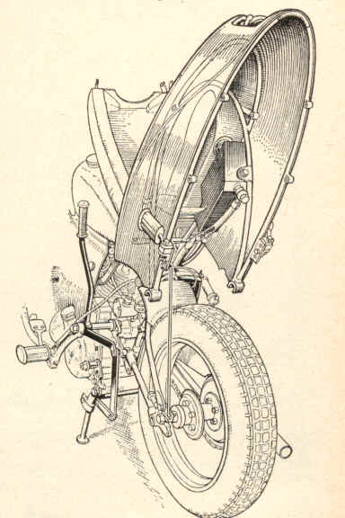 Series D Tail Section
Looking nothing like an engine, the lumpy rectangular thing might be anything at all. Only the two spark plugs sticking up out of the block and the brass-bodied Amal carb give it away. It's in pretty good condition, wearing mostly its original coat of Admiralty grey paint, somewhat chipped and worn as one might expect. It has all its tags and plates, being number 14 of a single batch of fifty made. The only thing that is missing is the ancillaries cover that covers the starter, generator and magneto.
I've not tried to start it yet, but there is no reason to expect it won't go - it was last started ten years ago. I'm stuck for someone to give me a hand with it tonight, so will still have it in the back of the Volvo at the Sodbury Sort out tomorrow if anyone wants to have a look at the strange device. Kim 5/3/02
Insofar as oils go, I have a buddy who successfully campaigned a Guzzi. He had gone to iron liners and was breaking the engine in at the track (fresh top end only). Couldn't get any power and was using Synthetic. Ended up doing the age old trick of throwing a teaspoon or so of Bartender's Helper down the carb to bed in his rings. Don't laugh, it really works. So, go with Dino oil until broken in.
You will most likely find that you must use gaskets on the covers, but this is because the covers most likely aren't flat. Next time you have the machine down all the way (may it be a long time), glue some 120 grit Al-Oxide sandpaper to a large, thick sheet of glass and true all the surfaces to themselves. For right now, you could get some engineers' blue and check your covers. If you get good contact, you would be alright to run Hylomar or some other non-setting sealant. Glenn Bewley 11/29/01
Never had a pushrod leak at the top. I've had the bottom
seals work there way up. Just pushed them back down with
glue.
I only use sealer on the timing chest, being carefull around oil
holes. I have valve seals with no metering wires and no smoke, so
I would leave them out and see. Agree with Ken, don't use
synthetic for break in. Non-detergent mineral base is what
many people use for ring break in.
I use a HD Dyna coil,
mounted inside the mag cowl. One thing to keep in mind,
instead of one end of the secondary winding being grounded as in a
regular coil, it goes to the second plug, meaning the current goes
from one coil pole through the plug electrode to ground,
then back from ground through the second electrode and back to the
coil. In other words a complete circuit using both plugs is
required to fire either plug, if one plug goes open the other
cylinder won't fire either (the affected cylinder can have it's
plug wire grounded to get you home). The Dyna coils come in
different resistances, get one that falls in the Boyer spec
range. You will have a wasted spark but it has never been a
problem. Paul Zell 11/28/01
(1) length of 24" ( 610mm) long x
5/8" (16mm) dia. threaded rod. eg 5/8BSF, 5/8UNF or M16
(2) lengths of 10 1/2" ( 267mm ) long
x 7/8" ( 22mm ) OD polished stainless steel tube. Wall thickness
not important but suggest 16SWG ( 1/16", 1.5mm ).
(2) stainless steel full nuts to match
threaded rod.
(2) stainless steel dome nuts to match
threaded rod.
For a 1/4" ( 6mm ) length reduce the hex. on all nuts to a diameter equal to the ID of the tube.Polish the nuts. Insert threaded rod thru' upper front s/car mtg. lug and equalise, spin on the full nuts and tighten, slid on the tubes ( locating them onto the reduced diameter ), spin on dome nuts and tighten. It took longer to type this than to make it. Jeff Bowen 05/06/01
1. You can shoot digital photos of
the original decal positioning on all the parts.
2. You can reproduce Every decal on a
motorcycle.
3. After shooting the paint, apply the
decals, by grabbing images of motorcycle parts in the
digital camera and then overlaying the Original digital images
to perfectly position the decals.
4. After the decals are in
place, shot clear over them.
Cost? $150 over the basic paint job.
Standard bearings with quarter inch balls
measure .640" in height when assembled. The taper roller
bearings that I posted the numbers of are .510" overall.
So theres a .130 spacer needed somewhere to get back to standard
dimensions. Trevor 12/29/00
I can't count higher than 50 so everything else is academic. I'm sure there are some prewar statistics I don't know (TTR's). There were about 117 Red Vincents and 80 Series B Black Shadows, including 4 that were sold with "Vincent" embossed cases and Brampton forks. They also made Touring Shadows and Comets. Experience has taught me that rarity and value do not go hand in hand. The most common one seems to be the Basket Case that someone is going to fix one day. If I've erred, let me know as some of this is based on "Lore" I've heard over the years. Somer Hooker 12/09/00
The room and cases should be warm, about 78
- 80 degrees F. I prefer to start with the cases
upside down, resting on the tips of the big cylinder head studs,
working my way around and down towards the studs . This way the
bottom messed up spots when flopped over onto the bottom are
easily touched up, and are not seen anyway. Warm the cans
in water to body temperature before use to get more consistant
flow and pattern .
Some nozzles do better than others so swap
the good one to the next can. Blow clean with the PJ1
through the nozzle in both directions. Light fog coat
first, allowed to setup a few minutes to create tight base
tooth. Now, walking around the motor, this sitting on a
bar stool - about level with your belly and well flood-lit -
spray with fairly rapid but smooth passes left to right and back
again, distance 12 to 14 inches away. Light
overlapping passes across the case bottom {now upwards
facing you} keeping up that smooth
motion as you walk slowly yet steadily around the motor on its
stool. Keep a keen eye out for any
signs of a run developing - thus the need to
use only light repeated passes while moving constantly - all to
limit the thickness of the paint deposited in any one place.
When you reach past the halfway down location - stop. Rest a moment. Now a test of your strength ! Grasping the long studs now beneath, now focusing your effort, you raise upwards the wet and glistening case and while held aloft you rotate it so that studs now point upwards -and sit it back down on its bottom without marring its shiny coat. Take up the spraying process once again where you left off a moment earlier, the paint still wet from the last pass. Blending in an overlapping pass, continue to walk around as before. Work upwards until you are covering the cylinder mouths and have painted all covers and every crevace with care.
The final judgement to stop is a magical moment when that glisten is apparent over the full surface like a wet piece of hard candy. You cannot go back over it to just correct a small thin spot because the overspray will futz up other areas, even the other side and kill that flawless glisten so desired. Make the decision and leave the room, allowing no one to enter that room for 48 hours.
Leave the floods on to warm the surface,
thus assisting it gassing off. The final bake off will
need an oven temperature of 170 to 200 degrees F. for
about 4 hours continous. I leave the oven door cracked
open about 1 inch to allow the paint vehicle gasses to
leave the surface freely. Allow it to cool until cold
sitting undesturbed in the cold oven, its door propped open
about 3 to 4 inches to allow a more gradual cooling process
. Sid Biberman 11/27/00
In the case of the mudguards, I experienced some "crazing" whereby the powder appeared as though it cracked under a bolt head, and turned white.The headlight and forks turned out great, no bubbles at all.
I am now in the process of doing the procedure over again. To strip you can utilize the expensive aircraft stripper with very good results. Plus, MEK (methyl ethyl keotone) also works, but it is best if the part is completely submerged. The aircraft quality stripper works (n my estimatio) best, and you won't have to worry about blasting. If you will brush the stripper on, in one direction, in a warm room, then cover it with Saran wrap (a clear film) it will be most effective as chemicals will not evaporate immediately.
You do have to worry about is masking the part before coating. Make sure you mask all flat gasket surfaces, plus plug any holes as the process is electrostatic and will attract the powder to oil galleys, threads, holes, etc. Removing it with a file is possible, but tedious. Overall I would not be afraid to powder coat a set of cases (Black for example) or even clear with proper preparation.
On flat areas (such as the chainguard) you will experience some orangepeel (waviness). The problem can be addressed by actually sanding the powder coat and spraying with a clear lacquer. I did mine with good results.
I just polished the fins of my cylinders, spent HOURS cleaning off the residue, and then had the cylinders coated black. White the paint is wet, the powder coater wipes each fin with his finger and leaves it shiny...I'll do the same with my cylinder heads.You can see the same procedure on custom Harleys in the bike magazines today. To my eye, the fins now sparkle and look great. For those in the Midwest looking for a conscientious coater, I recommend Indy Powder Coating at 317 244-2231 Carl Hungness 11/19/00
All was well until last week, when I disconnected a carb and found the float bowl full of fine rust. Looking through the filler opening with a flashlight revealed that rust had formed beneath the Kreem, causing big sheets of it to separate from the tank's roof - I pulled out a couple of large sections through the opening.
The situation was fraught with peril, since
most things that remove rust or tank coatings can also be relied
on to damage exterior finishes. With input from Kreem
Inc., Allan Johncock and Somer Hooker I determined that Kreem
dissolves in methyl ethyl ketone (MEK) or acetone. Both
these will attack paint, so I needed a way to protect the finish
during the operation.
Fortunately, the Kreem people had
useful advice: use a product called Liquid Overspray
Mask. This is made by 3M and others, and used in auto body
shops. It's a water-based coating that you brush or spray
on, and when dry it protects a surface from paint spray (and
acetone - I checked). The good part is that it's water-soluble,
so cleans up easily afterwards.
After giving the tank a couple of solid coats of LOM, I dissolved out the Kreem with repeated doses of acetone. It took most of a gallon before the Kreem was all gone. Naturally, having protected the paint I managed to do all this without spilling a drop of acetone...
Next step is to remove the rust with a phosphoric acid solution - the tank's been sitting for a couple days filled with this, and should be about derusted. To protect the exterior from the acid, I gave it a thick coating of wax.
I'm planning not to recoat the tank, as the coatings seem to cause big trouble unless applied perfectly - quite possibly I would mess it up just like the PO did. Instead, I figure on keeping the tank full to avoid condensation. Dave Hartner 10/27/00
I drained the acid this evening and found some rust remaining in the tank, so I put it back in at a higher concentration. May take a few more days, though. I'll report on the eventual outcome.
Don't know why Kreem sometimes holds up well, other times not. Most problems seem to relate to inadequate surface prep, but apparently you can get away with that sometimes. My tank was probably coated about 11 years ago, though, so the Kreem had plenty of time to loosen. Dave Hartner 10/27/00
Everyone knows half a thousand is 500, but the bike I was riding about nearly 30 years ago had more than one onlooker looking mystified, to say the least.
Perhaps I'd better start from the beginning when Eric Winterbottom was successfully campaigning a single seat racing car with a 1,000 cc Vincent power unit and wanted to switch rapidly from 1,000 to 500, in order to compete in two classes in one day.
The problem when presented to Stevenage was soon solved. The rear rod, piston, barrel and head was removed and a few necessary bits and pieces added or subtracted, plus a spot of re-balancing and hey presto!, a quick change power unit mounted VIA the identical bolts, brackets, etc.
With a compression ratio close [sic] on 14:1,
the Lightning specification single-lunger needed a diet of
ethanol/Benzole/petrol, on which it motored along quite
respectably, if not sensationally. In order to run it in and
check for unseen snags, it was mounted in a standard bicycle using
a non-operative rear head and barrel to provide the UFM rear
attachment point.
Externally it looked like a standard Twin except for the following omissions: rear carburetter, rear exhaust pipe, rear plug lead.
First, how'd did it go? Strangely enough it felt exactly like a Twin with the rear plug lead missing, no carburetter and no exhaust pipe--and sounded like that too. Handling was inferior to the Comet and maximum speed was also down on a similarly tuned standard-type 500, 100 mph only coming with reluctance. It was of course heavier than a Comet with more transmission drag and a much less rigid flywheel assembly. The bottom half of a Comet is probably the best in the business, with a tremendous margin of safety (look at Brian Chapman's 'Mighty Mouse').
My first contact with the unsuspecting public
was whilst thumping along towards Cambridge at about 80
plus; I overtook a 998cc side-valve AJS Twin. Stopping
a few miles further on to check for anything loose, etc., the AJS
man stopped to enquire [sic] after my, or my bikes, health.
I replied that my rear carburetter had fallen off, but I would
proceed with one, which I did
without more ado. I met the same chap some time later when
he came to work at Vincents [sic]. He lost no time there
reciting the story of the Vincent tester who carried on testing
the bike even after the carb and, whats [sic] more, the exhaust
had both fallen off!
The next incident was with a caller at my
house one evening, who had frequently badgered me for a ride on a
Twin. To his surprise, he was actually asked on this
occasion and was soon astride kicking lustily. A couple of
stalls and he was away, returning 10 minutes later smiling and
full of enthusiasm, not wishing to appear ignorant or ungrateful
and having experience
of nothing better than a 350 AJS, plus a long line of less potent
devices, he chose to make no comment--only gazing somewhat blankly
at the rear cylinder head!
It was at the local motor-cycle club night where he really got the odd looks, enquiring [sic] if it was possible to run a Vincent Twin without a carb, exhaust or connected-up plug on one cylinder.
Finally I connected up the exhaust, fitted a
carb and stuck a plug lead on and rode to a local friendly
motor-cycle dealer, complaining of loss of power. Still
relatively new to many motor-cyclists, a Vincent Twin was always
guaranteed to bring out most of the curious of any motor-cycle
shop, this one being no exception. Advice and assistance was
volunteered from all
directions.
Spark and fuel were checked and found
OK. However, a compression check soon had eager hands
unscrewing plugs, inspection caps, etc. By which time I had
withdrawn from the hum of activity. Suddenly an excited
voice said 'The
piston's gone'. 'Gone where' said I. 'Damned if I
know, I only know it's bloody gone' came the reply. 'What
about the rod, that's gone too! 'Not much I can do here
then, better button it up and I'll get it back to Stevenage' said
I. 'I'm going that way' said the Foreman, 'I'll come with
you in case you pack up completely'. 'Thanks' I said,
kicking up and accelerating off.
The Foreman never did catch up with me, although, as he related to his Fitters on his return: 'My Inter Norton was absolutely flat out for nearly 25 miles, just imagine how those bloody things must go on two pots--and what a way to ride a bike with a broken up rod and no piston!'.
You'll want to know how it went in the car, no doubt. Winterbottom's comment: 'Bloody awful, like Half a Thousand!'
Ted Davis 10/13/00
Build done just in time to make rally. Literally 3 min run time before shipping. First mile done on grass airfield at Ken Bloomfields farm north of Coventry. 150 miles to ferry. Another 50 or so getting settled before parade lap. Scraped the pipes @ Sulby, full throttle on the mountain.
Currently using 15/50 Mobil 1, oil temp runs 145F on 90F days, changing to Amzoil 20/50. No oil leaks, zero oil from breather, 50 plus rear whl hp@5500, 61.5 fp torque@3300. 2500 miles to date, engine is strong and quiet.
Does anyone know why I should not continue
to use synthetic oil or plugs in the cyl oilers?
Steve Hamel 9/14/00
A very good description of oils and their uses (what the numbers
mean, additives etc.) can be found at
http://www.edmunds.com/edweb/editorial/features/dino_juice/index.html.
Steve 9/14/00
Of course big ends will skid and seize go whilst using Mobil F1, or any other synthetic, because in its action of lubrication, it removes built up sludge and gunge which then allows worn rollers and balls to skid and woggle freely. This is especially so in the well known situation with engines that have breathers and elephant trunks all over the place that attempt to relieve the foggy oil mist generated by worn bearings. The big end of HB and the big ends of Private Benjamin seized after some 4 to 5,000 very hard miles where no respite had been given. Pte Benjamin mostly pulling Jet 80 with oversized ET50/2 installed. When split open, the crankcases were as clean as new. In fact they shone as if polished. All surfaces, bearings and cams had good surface film and there was no sign of carbonise sludge despite the intervening years. In HB, all bearings were replaced, and running in was done with Mobil F1 and after 3,000 miles running in, she was thrashed hard almost from start up. We also installed a two start pumps. What I did notice was that after five years there was little breather haze and low oil consumption. With standard oils, oil changes should be carried out as per Rider's Handbook, but with Mobil F1, all one needed to do was to top up the tank on occasions with very long oil change intervals. Oil filters still being changed regularly. It all depends on the individual's approach to the machine and how one cares for an over priced almost irreplaceable pleasure asset. Even my Kawasaki Vulcan went better on Mobil F1. It's four valves per cylinder and twin spark plugs never giving trouble despite being used flat out almost everywhere.
This is long winded, but why pay so much
for machines and parts, then neglect the lubrication. I
always considered that when it comes to lubricants, most people
opt for cheapness under the guise of originality, but for me,
the extra cost was worth it when considering how synthetics,
stick to the Balls. WOR 9/14/00
You're right in your'e analysis of the
effects of sulfur in gasoline (well actually the combustion
product is SO2 and not SO3 and forms H2SO3 not H2SO4 on contact
with moist air. However the effect is the same). It's actually
technically fairly easy to remove sulfur from gasoline, at least
down to less than 10 parts per million..This can be done through
simple hydrotreating, a
process which removes sulfur as H2S. The
resulting gasoline product however loses octane (particularly
RON) as a resut which must be regained through other
refining processses (isomerization for example) or addition of
ethanol or MTBE
as an additive (the latter soon to be banned
for evironmental reasons). There is a significant cost to do
this though and refiners will resist the investment to install
equipment to do it unless required. They are in business
after all.
In the USA the pressure to "do it" is
politically now very strong and comes from the
environmental lobby. The bulk of SO3 in the air is
actually formed mainly from fossil fuel combustion such as
coal in power generation and it forms the imfamous "acid rain".
Gasoline combustion is however a contributor. This presssure for
clean up will continue to be applied, driven along by
legislation in California, the leading state
in this area of legislation.
The net result of such legislation is that gasoline will continue to get reformulated to meet the new laws on emmision control. This reformulated gasoline ("RFG") is the one we complain about w.r.t our Vincents regarding engine timing, carburetter settings, valve wear, melting tank sealants etc. etc.
Well it ain't going to go away as you chaps
in the U.K will find out soon enough, so you all have to
decide which side of the fence you're on! Here in the USA
the design of Mr. Vincent and Mr. Irving has proved remarkedly
resiliant to changes...with a little added
ingenuity! Tim Holcroft 9/14/00
Regular motor oils reallyt are the best cost effective compromise of these duties with variation provided for certain conditions such as winter/summer grades and certain engine bearing characteristics. As the duty of an engine becomes more specific (e.g. racing under extreme conditions BUT for short periods) you can formulate oils for just that service but they will lack long term maintainance of their properties. Remember Castrol R?
In a modern engine the job becomes a little easier because they are intrincically cleaner, bearing materials and design are much improved with very close working tolerances, and they run over a narrower temperature range. No doubt synthetics can do the job.
I guess my point is why would you go to a synthetic on a Vincent when regular oils will do the job, certainly far better than the oils available than at the time when it was in production, and risk an expensive failure? Is there a dramatic cost saving to be realized here or are we just embarking on a theoretical excercise into a realm none of us really understand. There is a phrase for that activity but it escapes me just at the moment.
Arthur Farrow's Dad, who was an expert, would no doubt have had
it right if, as Arthur suggests, he would have said you can
probably use anything, but steer clear of sythetics. Tim
Holcroft 9/14/00
If you check out the D.I.D. line, you will
find that there are differences in the thickness of the plates,
and this is reflected
in both the price and the strength of the
chain. I don't think you need the top of the line for
Vincent power, considering that
these are made for bikes with two to three
times the horsepower, but if you've opted for 1/4" sprockets you
have retained
the option of using the very strongest
0-ring chains available. And if you will be able to,
should you have to use a chain of
greater width in an emergency (on desert
bikes, it used to be common to deliberately use a rear sprocket
narrower than
the intended chain, so it would be
self-centering if there was a quick-stop for a flat repair, or
the like). It should go without
saying that the strongest 1/4" 0-ring today
is stronger than ANY chain short of an anchor chain of the
post-war era. But
strength isn't the reason to go to an 0-ring
chain--it's the lifespan, since, to a great extent, the inside
lubrication is sealed
in. The outside of the rollers still
need lube, and the plates also are still exposed to all the
terrible stuff out there. And the
0-rings are not impermeable -- the Cassiar
Highway killed an 0-ring chain of mine in a day, being mostly a
slurry of calcium chloride and mud, with the combined attributes
of valve grinding compound and my mother-in-law's personality.
Speaking of strength, although 100hp is
generally considered the practical limit for longevity in
motorcycle drive belts, I
suppose it's possible that by reducing the
width by 1/3 you compromised the strength of the belts to where
they couldn't
handle half the horsepower, either by
destroying the integrity of the weave (as you suggested) or by
just reducing by a
significant amount a structure whose
strength is dependent on a multiple of its surface area rather
than an arithmetic factor.
Hope you're still awake after all that.
Good luck, j caraway
I am still not sure why the belts simply snap, (after nearly 10,000 trouble free miles) but now since I have to replace much of the bottom end of the machine, I have decided to forego my belt conversion and return to a chain. I have been told that either a "520" or a 525 O'ring chain can be made to fit if I narrow up the stock Vincent sprockets to fit inside the chain's links. Does anyone have experience with the O'ring chain modification.?.Which chain should I look for, the 520 or the 525?
I dearly love the smoothness of the Harley belt, but it now occurs to me that just possibly the belt is sealed in manufacture and when I narrow the unit, I am disturbing the seal. The Harley belts are intertwined with Kevlar, and the strength of this material is literally unbelievable. As I have mentioned in earlier writings, a single strand of Kevlar is strong enough to hoist a full size Harley Twin off the floor.
At any rate, I'll leave the Harley belt test to another time and return to a chain, but this time I'd likew to run the largest O Ring chain I can, so all suggestions are welcomed.
Best, Carl Hungness 8/06.00
My problem with the heated grips is similar to most other problems I've had with the bike, (self-made problems that is) inasmuch as I have run ALL my wires inside the handlebars in order to maintain the clean look I really prefer. Consequently, I continually break the connections as not only my throttle side turns, but I had a Twist-Dip to operate the high low beam, and have broken both sides on more than one occassion.
My specific question is, are there any of you out there who are successfully running heated grips? I'm looking for advice, and tech info. I need the grips heated as I have very poor hand circulation due to surgeries on my hands.Has anyone had experience with the BMW heated grips?
I am currently installing a Harley-Buell Turn signal-horn-hi-lo beam module on the left side in place of my great old Twist Dip and want to revamp my heated grips once again. Carl Hungness
I had to do it twice because I did not want to use a proper enough fastener for the distance tube at the two fastening ears at the rear, The nut vibrated off, lost the bolt and the tube and then more cracks appeared. This weak spot was warned about in "Know thy beast" and many other places. Now I have a very carefully measured-up distance tube, a new bolt, serrated discs and a ny-lock nut and no problems.
My tank developed the first crack (should have been the only one!) after the final new paint job of the tank - off course! So in my repairs I did not want to destroy the finish either.
Take off the tank and thoroughly clean the inside with household dishwashing detergent and lots of water. In the end I left my tank on the lawn with the garden hose flushing and flushing. ( see safety item next message - ed)
In the crack I cleaned just approx 10 mm of bare steel on each side of the crack and quickly discovered that this was not the firs time this area had been repaired, -both with welding and brazed. The brazing repair rules out any new welding... (If one welds close to an area that has remains of bronzes from brazing, the bronze will have 200 -300 degress lower melting temperatures than the fusing steels and the bronze will flow into the steel weld and alloy.) The result will be a porous brittle material that will have to be removed totally.
Use a top degree silver solder melting temp in the 500-600 degrees C range; safe for the old brazing and the steel. If the crack is clearly visibly and wide open, use a fillet making silver solder. If it is a tight crack, use a cappillary type (a good plumber or model engineer will know). You may find you need both types. Absolutely do not go for the tin/silver solders of 200-300 degree C range. They are not strong enough..
Clean and clean and clean out the cracks to bare metal; if possible with a disk on a Dremel or some jewelers files. Wash with acetone. Make a jig or a stand or just a stable holding for the tank so that the crack is at the uppermost position. If the crack is long or you have several cracks you must do this in several separate turns.
Make sure your tank lid is leaking a (vent hole open) a bit. Fill the tank totally with water and place it , crack thoroughly cleaned at the top. Some water will seep out through the tank lid.. I also applied some wet rags of cotton around the spots to be repaired to help cool down and protect the paintwork. You won't need these if the tank paintwork is of no importance.
This is "miniature surgery" , very long preparation time. When all this is prepared properly, it is just applying some heat and the laws of physics secures a top result - if you remember to keep it vibrationless afterward.
Apply liberaly the recomended flux powder, made into a slurry...
I use a fine tip Oxy acetylene torch, heat gently; the flux will turn dry, the water will rumble on the inside; the cloth will hiss on the outside and the tank will try to squirt its water as the little air pocket on top expands. (At this stage you will be grateful the the steam coming though the crack is dry water steam and not gas....) The oxy acetylene is needed to be able to quickly heat a bit above of what is needed to melt the silver solder. Remove the flame tip and the cold water and rags will quickly make the crack into a "suctioning " crack. Apply the cappillary silver, reheat and do the next centimeter and in a very short while the crack is tight. Clean up, look it over, and if possible fill the remains of the crack with more silver solder to a wide ridge so as to give it a better contact with the surrounding steel.
Pressure testing? : -Block off any vent holes, remove taps, keep the tank filled with water; a pressure gauge in one tap and a pump connection in the other tap and pump away to what pressure you would want.. Ouch!
I mean a motorcycle petrol tank is not a pressure vessel, never meant to be, and any applied pressure might do harm. I usually just put my mouth to the filler opening and blow to "feel" any leakage. Much better to apply some oatmeal to an outside cleanned supected area , water inside; blow gently and any seepage will show. More silver solder!
In the end clean off any excess material and repaint, polish up the beautiful black and (almost?) nothing shows.
Per Erik Olsen
pereo@east.no 5/27/00
Very well presented set of instructions, especially noting the variance in heat ranges of silver solders - Johnson Matthey Easiflow No.2 is good for this (630') and also available is a matching Easiflow flux... Johnson Matthey are on 0044+ (0)20-8804-8111, address Jeffries Road, Enfield, Middlesex, EN3 7PW...
Silver solder has excellent capilliary
creep properties, allied with fair strength, plus it flexes well
with the work, whereas welding gives more fracture-prone
hard-points (weld prone to being stronger than its surrounding
host metals, especially when they've been annealed with
thehigher temperatures involved in the process...). Hope this
all helps... Tigger. 5/29/00
Rx.
My
paint
man
uses the regular water transfer decals. Some clears will attack
them. Every time he gets a technique figured out, the EPA
changes the formulas of the clear. Put a decal on the bottom and
experiment. Also if you are adept with a paint brush go around
paint black over the small border around the transfer. Otherwise
there will be a small white border around it. The vinyl "peel
and stick" are about one mill thick. They will stand proud once
applied and cleared. I guess you could clear it alot. I think
the water transfer ones are best. Make sure they are new too.
Some of thee old ones seem to deteriorate with age. Tank
covers are cheaper! The above ramblings are not
nesesarily those of a sane mind. Somer Hooker
4/24/00
The "nutshell" version of the application procedure involves applying "varnish" (as the adhesive) to the back of the transfer and letting it "touch dry" before removing the thicker backing paper (leaving the tissue in place)and applying to the applying tank. The tissue paper is left on the transfer after installation and is left there until the transfer dries. The tissue is then moistened and removed and the remaining tissue adhesive sponged off.
It sounds very easy, but itis not in
practice. The newer waterslides are infinitely easier to
apply properly and therefore are more likely to produce a better
finisehd product, in my opinion. Perhaps your friend
remembers the
waterslides available in the '70s which were
not true reproductions of the original?
Alcohol? I have used "Spirit fit" Achilles Wheel transfers. The mixture is 75% methanol and 25% water. They tended to wrinkle during drying. Use waterslides. Russ Williams 4/24/00
This appears to be the transfer type I have. Anyone tried
these, and what is methylated spirit? Paul Zell
4/24/00
I apply either type in the following manner(short version):
1. Split paper with transfer from cardboard(needed for production
and packaging only)
2. Make sure where exactly the transfer is going. Put on
some masking tape pieces as supporting markings to help in the
final placement (=trial runs).
3. Paint the rear of the transfer only (gold size = splendid !!!
as this is REAL gold and will have the exact colour and stay that
way; and be a perfect match for the gold size lining to be
applied later.... ) Paint with Clear Humbrol hobby
paint... this is clear one step Poly Urethane , will take
any clear coat without lifting or "boiling" later....
4. The advantage of this varnish is that it is reasonably slow
drying and comes in a handy size box... :o)
5. When the Humbrol is tacky, place paper with transfer
aided by masking tape in the right spot. Sorry: Get it right
this first time! (therefore the "dummy-runs" and masking tape !!)
6 .Use back of finger nail and "polish out" the transfer and
get it well stuck.
7. Let it dry, if you have painted another spot with the
Humbrol you'll get an idea as to when "tacky" and when all dry..
Backin paper still there.....
8. Make up an egg glass, cup, or a saucer with half and half
water and red spirit(metylated spirit= for use in petrol during
winter for removing carburettor icing) or methanol and dab the
paper in this solution with a cotton cloth on the backing paper
until it is transparent...
9. When the spirit (alcohol) soluble paper-transfer glue is
"liquid", slide the paper backing off and carefully clean
the finished transfer with the rest of the alcohol solution.
10. Finished!
The reason for the paper backing lies in the screenprinting process of making transfers(decals).. without the paper and the alchohol solulbe glue, the transfer will have to be much thicker (a separate base) and many more coats of clear will have to be applied to give a coating thick enough to be sandend down again for the last all-even-shine...
Sorry for the length of this, but not many know of the old ways.....Please contact me if this needs clearifying or further arguments.. :o)
PS I use the same materials for REAL gold
linings...............(no brown "gold" paint)
Per Erik and F/10/AB/1/17 4/24/00
Timing your Vincent with a strobe lightis now possible. It's fun. It's easy, and it's free. Just follow these simple, easy steps. This procedure is intended for distributor models but will work just as well with a magneto with some slight modification (different timing marks on the fibre gear and the addition of a spacer).
The first thing to do is put the bike on its rear
stand. Next, remove both of the spark plugs. Remove
the crankshaft quill and attach a timing degree wheel to the
crankshaft. Locate top dead center using No. 1 (rear)
cylinder. Remove the distributor (or magneto) gear cover. (If you
are very nimble, try removing the gear cover without removing the
exhaust pipes). At the bottom of the inspection cavity there
is a casting edge that comes very close to the timing gear.
This casting edge will become your
indicator line. Using No. 1 (rear) cylinder, rotate to its
compression stroke, and referencing your degree wheel, locate (by
rocking back and fort) until top dead center is attained.
This is your 0 degrees or TDC reference.
For the next step, you must first remove all oil film from the fibre gear (use brake cleaner or other solvent). This will allow the marking paint to adhere to the fibre gear. Using the casting edge as an alignment sight, scribe a line on the fibre gear. Next, enhance the scribed line with white paint, or light coloured fingernail polish. Now, rotate the motor backward to 50 degrees before TDC. Then, slowly rotate the motor forward to 40 degrees before TDC. Scribe a mark on the fibre gear. Rotate the motor by 4 degrees to 36 degrees before TDC and scribe a mark on the fibre gear. Next, apply white paint on the scribe marks on the fibre gear for easy identification when using the strobe light.
The next step is to make an inspection window. My Vincent has a distributor, so for this, I used quarter inch clear Plexiglas of about 6 x 6 inches which I purchased from the local plastic house. I used my timing gear cover as a template. I traced the cover outline onto the Plexiglas and then cut it out. For those of you with the original magneto, the timing gear inspection window will need a spacer to allow clearance for the auto advance unit. Cut two plastic windows from your template. On one of these, cut out the center about 2-1/2" to clear the advance unit.
After you cut your window/s out, mark your six mounting holes and drill them. You may have to file the holes a bit to make everything line up, but as with any traditional English vehicle, filing is well know to many mechanics. Remember, it doesn't have to be very pretty. It just has to keep oil from spewing all over the hot exhaust pipes, the timing light, and you. Attach the window using the timing cover screws. Replace the spark plugs and wires. Remove the crank timing wheel and replace the quill. Connect the strobe light trigger induction probe to No. 1 rear cylinder and connect the red (+) and black (-) timing light power to a 12 volt power source (battery). The fibre gear turns half as many revolutions as the crankshaft, or, in other words, for every one revolution of the fibre gear, the motor turns two revolutions. Because of this, 10 cam degrees = 20 motor degrees. Simple hey?
Timing the engine: Start the engine. At idle,
the timing should indicate near the TDC mark. Increase the
engine RPMs slowly. You will see the auto advance begin to
engage. When the motor is turning between 2500 and 3000
RPMs, the advancement should be at full. Sight down the
casting line with the strobe light and observe where the 40 degree
mark lines up. Ideally, the best timing is between 36 and 40
degrees, but will depend on the compression. Loosen the
pinch bolt (distributor). Rotate the distributor to the timing
your model requires. Tighten the pinch bolt, and again
recheck the timing in case anything moved.
You may also want to check the degree of timing for the
front cylinder following the same procedure as you did for the
rear cylinder. You might want to use longer marks to
indicate that this is for the front cylinder. Timing the
front cylinder will indicate how accurate your ignition cam
is. My own ignition cam was 3 degrees off. I wanted to
have electronic ignition to eliminate the points, and correct my
cam timing offset. I have improvised and installed such a
unit on my bike. I will describe how I accomplished that in
my next article.
As many of you know I fitted a Sportster belt to my Vincent twin a couple of years back and have since broken three belts for varied and sundry reasons I am not really sure of. I believe I had the belt far too tight on one occassion and as reported, after dis-assembly after breaking the last belt I discovered the ESA was in fact "on end". It has been reported that it would be impossible to run the bike with the ESA in this position and not notice the vibration, so possibly the ESA found its position just as I broke the last belt.
I have now discovered that the pylleys themselves wear after 60,000-80,000 miles and it does no good to just replace a belt (on your big Harley) . There are bikes on the road with 100,000 miles on the belt, but my local dealer has noted that when he replaced the belt on a bike with 60,000 miles on it, it broke the new belt within a couple of thousand miles.
My pulleys look like they are in good shape, I know the rear wa new, the front was used, but it looks fine (as opposed to a worn one I have just inspected at the Harley shop).
I am nearing the end of my patience
with my belt conversion now, and considering reverting back to a
chain. Carl Hungness
The felt you require is used by medical people and is available from medical suppliers.
Felt is made by pounding wet wool till it forms a matted 'felt'
it can be pounded to form many shapes like hats.
Wool does absorb water but it also dries fairly quick with no side
effects. It will not absorb water if it is oil, grease or lanolin
(as on the sheep's back) soaked.
I cut my felts with a washer cutter with the two blades sharpened by stoning on the outside of the outer blade and the inside of the inner blade the profile of the cutter blades is a rounded tip. The centre of the washer cutter is a sharp point as in a scriber instead of the normal drill point. Hold the sheet of felt on the drill press table with some clamps and wood backing. Revolve the cutter fairly fast 700rpm and with a gentle pressure and facing east you should get washers and be able to make enough to give to your friends when you next ride together.
As to your other problem with the speedo
right angle gears. To change from the steel gears to the
nylon gear box you will have to change the main frame of the
chronometric movement. This is a fairly major undertaking and I
would not recommend it as an
exercise for an easy evenings work. The steel gears are abought
half the size they should be for the job and I
am afraid to say the right angle drives on the back of some
Japanese Speedo's are a much more substantial item and they can be
found with a slightly less of 90 degree angle which gives a nicer
lay of the speedo cable.
To adapt a Jap gearbox to a chronometric movement is a major undertaking. The nylon gear box from Smiths can be found on the back of old Rover 2000 and Austin or Morris 1100 (export model) cars Speedo's and it too is not up to the job the nylon gears soon shed their teeth but of course this expensive gear box can be easily changed for a new one once worn out.
The best and easiest fix should the (steel gear's) box reach the
end of its life is to change the main frame of the chronometric
movement for a straight drive one and connect a longer speedo
cable so that the cable now comes straight out of the back of the
speedo and you can finish the job nicely by bending the bracket to
lay the speedo down a little. I think the original is
too vertical in any case. It is also recommended that Speedo cable
should not go through any less of a radius than 9 inches.
Andrew Rackstraw 4/05/00
Neville Higgins, known as the Professor in the VOC for his highly analytical methodology in general, commented about the modification in the same MPH as he saw my story before it was printed, and therefore had an opportunity to comment on it .
Neville gave us a fine little test to see if our stock breather timing was correct, and I just had opportunity to test mine as I just replaced my cams and lifters. Overall, Neville's formula proved to be spot on for my bike, so I moved my gear train back to its original configuration. I had also modificed my "breather tube" per the Phil Irving suggestion to "widen the slot" . I did so and as expected the wider slot does allow the breather timing to start a few degrees earlier, and close a bit later.
The main point here is not my tube modification, but Neville's
timing diagram that shows us where the breather starts to open and
starts to close. In all due respect to Dick
Busby and his fine mechanical accomplishments (the Vincent world
was lucky to have him ) I am in favor or utilizing Neville's
timing diagram to set breather timing on my bike. I'm anxious to
try out the system. Carl Hungness
Ladies & Gentlemen: I had an expensive trademark search done a few years back regarding the Vincent name, the other associated names such as Black Shadow, Black Lightning, Black Prince, Comet..etc..
I can tell you there is a Black Shadow bicycle, artist's brushes utilizing the name and so is a musical instrument company. There is a Black Lightning archery bow, Lightning ammunition and hose clamps, and for the Black Knight you'll find bicycles to tobacco. There is a Comet motorcycle and more artist's brushes names Gray Flash and the Buddy L corporation has a Black Shadow toy.
David Matthew Scott Holder holds trademark to the name Vincent (for motorcycle usage) in the United Kingdom. Period.
There is also a rapide bicycle being made by Raleigh Cycle of America.
But if you start looking thru the directories , you'll find Lightning ammunition, animal laxatives, bicycles, carpet, caulk, guitars, hair irons, hose clamps, letter openers, one design of a sailboat, paint brushes, pistols, powerboats, recliners, recording label, sporting oods, tape sealers, wheelchairs, writing instruments. I could go on and on about the other model names as well. Under biscuits for example, you'll find some called "Prince". There is a Dodge automobile called a Shadow as well.
I for one am just glad there are enough real enthusiast about to supply me with parts for my Shadow. I can call up and order anything from an oil filter to, well, you name it.
Moral to the story: Keep riding them so you'll wear out parts...Sincerely, Carl Hungness
Be wary of blameing one piston or the other for this failure (seizure/holing) as none are safe or immune to the occurance , rather it is usually a mixture setting - and - or restricted fuel flow promoting a severely leal condition . Also high on the list of causes would be excess ignition advance . The flow fault is often as simple as a clogged filler cap vent hole or fouled filter screens on the fuel taps , or even not always opening both taps at sustained and elevated speeds .
The early original cork taps are always suspect at
providing sufficient flow for speeds above 60 -
70 MPH and never
for top speed runs . Larger bore lever taps and
opening out larger that cap vent is tops on the
list of serious Vincent riders as would closely
setting ones ign . timing . Incorrect jet sizes
, sticky floats and inlet manifold air leakage
at the male to female joint - paticularly
that last one is very common on older Vincents and to
never be toleated due to its directly leaning out of the
mixture strength . Many pistons have been cooked and
eaten - one after the other after replacement on the
alter of not correcting the original fault FIRST !
So to my fellow Vincent owners, don't try to top this. Please check those petcocks and think about an upgrade. ( I did, and I also put a little extra $ in the plate, the next Sunday). Ken Smith ( Phil. Pa. USA )
The problem when presented to Stevenage was soon solved. The rear rod, piston, barrel and head was removed and a few necessary bits and pieces added or subtracted, plus a spot of re-balancing and hey presto!, a quick change power unit mounted VIA the identical bolts, brackets, etc.
With a compression ratio claose [sic] on 14:1,
the Lightning specification
single-lunger needed a diet of Methanol/Benzole/petrol, on which
it motored
along quite respectably, if not sensationally. In order to
run it in and
check for unseen snags, it was mounted in a standard bicycle using
a
non-operative rear head and barrel to provide the UFM rear
attachment point.
Externally it looked like a standard Twin
except for the following
omissions: rear carburetter, rear exhaust pipe, rear plug lead.
First, hod did it go? Strangely enough
it felt exactly like a Twin with
the rear plug lead missing, no carburetter and no exhaust
pipe--and sounded
like that too. Handling was inferior to the Comet and
maximum speed was also
down on a similarly tuned standard-type 500, 100 mph only coming
with
reluctance. It was of course heavier than a Comet with more
transmission drag
and a much less rigid flywheel assembly. The bottom half of
a Comet is
probably the best in the business, with a tremendous margin of
safety (look at
Brian Chapman's 'Mighty Mouse').
My first contact with the unsuspecting public
was whilst thumping along
towards Cambridge at about 80 plus; I overtook a 998cc
side-valve AJS Twin.
Stopping a few miles further on to check for anything loose, etc.,
the AJS man
stopped to enquire [sic] after my, or my bikes, health. I
replied that my
rear carburetter had fallen off, but I would proceed with one,
which I did
without more ado. I met the same chap some time later when
he came to work at
Vincents [sic]. He lost no time there reciting the story of
the Vincent
tester who carried on testing the bike even after the carb and,
whats [sic]
more, the exhaust had both fallen off!
The next incident was with a caller at my
house one evening, who had
frequently badgered me for a ride on a Twin. To his
surprise, he was actually
asked on this occasion and was soon astride kicking lustily.
A couple of
stalls and he was away, returning 10 minutes later smiling and
full of
enthusiasm, not wishing to appear ignorant or ungrateful and
having experience
of nothing better than a 350 AJS, plus a long line of less potent
devices, he
chose to make no comment--only gazing somewhat blankly at the rear
cylinder
head!
It was at the local motor-cycle club night
where he really got the odd
looks, enquiring [sic] if it was possible to run a Vincent Twin
without a
carb, exhaust or connected-up plug on one cylinder.
Finally I connected up the exhaust, fitted a
carb and stuck a plug lead on
and rode to a local friendly motor-cycle dealer, complaining of
loss of
power. Still relatively new to many motor-cyclists, a
Vincent Twin was always
guaranteed to bring out most of the curious of any motor-cycle
shop, this one
being no exception. Advice and assistance was volunteered
from all
directions.
Spark and fuel were checked and found
OK. However, a compression check
soon had eager hands unscrewing plugs, inspection caps, etc.
By which time I
had withdrawn from the hum of activity. Suddenly an excited
voice said 'The
piston's gone'. 'Gone where' said I. 'Damned if I
know, I only know it's
bloody gone' came the reply. 'What about the rod, that's
gone too! 'Not much
I can do here then, better button it up and I'll get it back to
Stevenage'
said I. 'I'm going that way' said the Foreman, 'I'll come
with you in case
you pack up completely'. 'Thanks' I said, kicking up and
accelerating off.
The Foreman never did catch up with me, although, as he related to
his Fitters
on his return: 'My Inter Norton was absolutely flat out for nearly
25 miles,
just imagine how those bloody things must go on two pots--and what
a way to
ride a bike with a broken up rod and no piston!'.
You'll want to know how it went in the car, no
doubt. Winterbottom's
comment: 'Bloody awful, like Half a Thousand!'
Ted Davis